This is an optimized low-level Arduino library to read and write nRF24L01(+) registers by using a SPI interface. It should be used in combination with a derived class which contains higher level read, write and configuration functionality.
Connect the nRF24L01(+) to any Arduino board which contains:
- An internal or external 3.3V regulator.
- A SPI interface.
- 2 digital pins for CE and CSN.
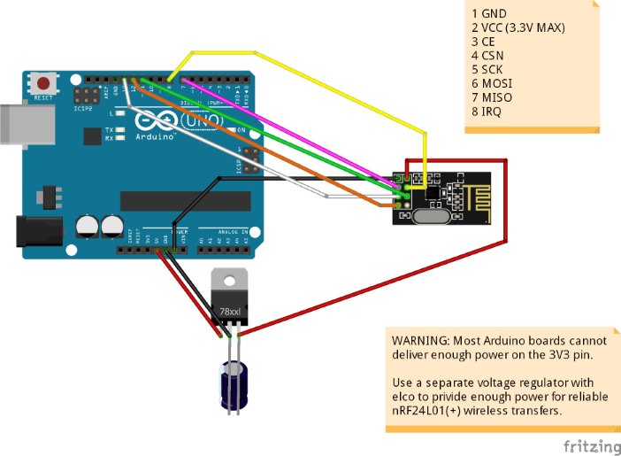
Retransmits or communication loss may occur when connecting the nRF24L01 directly to the 3.3V of an Arduino board, because lots of Arduino boards cannot deliver enough power for the nRF24L01 chip. This can be solved with a separate voltage regulator, or nRF24L01 power adapter.
A Nordic nRF24L01 or nRF24L01(+) 2.4GHz wireless transceiver connected to an Arduino UNO board with a separate 3.3V voltage regulator and 100uF elco:
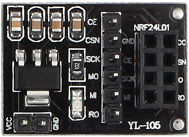
To increase communication reliability, use a nRF24L01 power adapter with a separate 3.3V voltage regulator, such as:
| nRF24L01+ Pin |
nRF24L01+ Function |
nRF24L01+ adapter |
Arduino UNO/Mini | Mega2560 | ESP8266 NodeMCU |
|---|---|---|---|---|---|
| +3.3V | 3.3V direct | - | 3.3V | 3.3V | 3.3V |
| - | +5V via adapter | +5V | +5V | +5V | - |
| 1 | GND | GND | GND | GND | GND |
| 3 | CE | CE | 7 | 7 | D0 |
| 4 | CSN | CSN | 8 | 8 | D8 |
| 6 | MOSI | MO | 11 | 51 | D7 |
| 7 | MISO | MI | 12 | 50 | D6 |
| 5 | SCK | SCK | 13 | 52 | D5 |
nRF24L01(+) Interface | RegisterAccess
The CE pin should be controlled inside the derived class.
The following libraries are used:
- SPI.h
#include <nRF24L01Iface.h>class nRF24L01Example : nRF24L01Iface
{
public:
// Constructor, initialize base class with SPI clock and SPI chip-select
nRF24L01Example(uint32_t spiClock, uint8_t cePin, uint8_t csnPin) :
nRF24L01Iface(spiClock, csnPin),
_cePin(cePin)
{
};
// Read status register
uint8_t readStatus() {
// Read status register
return readRegister(REG_STATUS);
}
// Read from config register
uint8_t readConfig() {
// Read config register
return readRegister(REG_CONFIG);
}
// Write to config register
void writeConfig(uint8_t val) {
// Write to config register
writeRegister(REG_CONFIG, val);
}
// Write to TX pipe (0) registers
void openWritePipe0(const uint8_t *address) {
// Write 5 Bytes transmit pipe
// Now pipe 0 cannot be used for receive
writeRegister(REG_TX_ADDR, address, 5);
}
// More functions such as read and write
// ...
private:
uint8_t _cePin;
};// CE pin to enable RX and TX modes
#define CE_PIN 7
// SPI chip select pin
#define CSN_PIN 8
// Create object and initialize with SPI clock, CE pin and SPI chip-select pin
static nRF24L01Example radio((uint32_t)10000000UL, CE_PIN, CSN_PIN);// Read status register
uint8_t status = radio.readStatus();
// Read from config register
uint8_t config = radio.readConfig();
// Write to config register
radio.writeConfig(0x08);
// Define an address pipe for transmit
const uint8_t pipeAddress[5] = { 0x55, 0xa5, 0x5a, 0xaa, 0x99 };
// Configure write pipe0
radio.openWritePipe0(pipeAddress);- Start the Arduino IDE.
- Download the latest version from:
https://github.com/Erriez/ErriezNRF24L01Iface/archive/master.zip - Click Sketch | Include Library | Add .ZIP Library... and select this ZIP.
- Run the example.