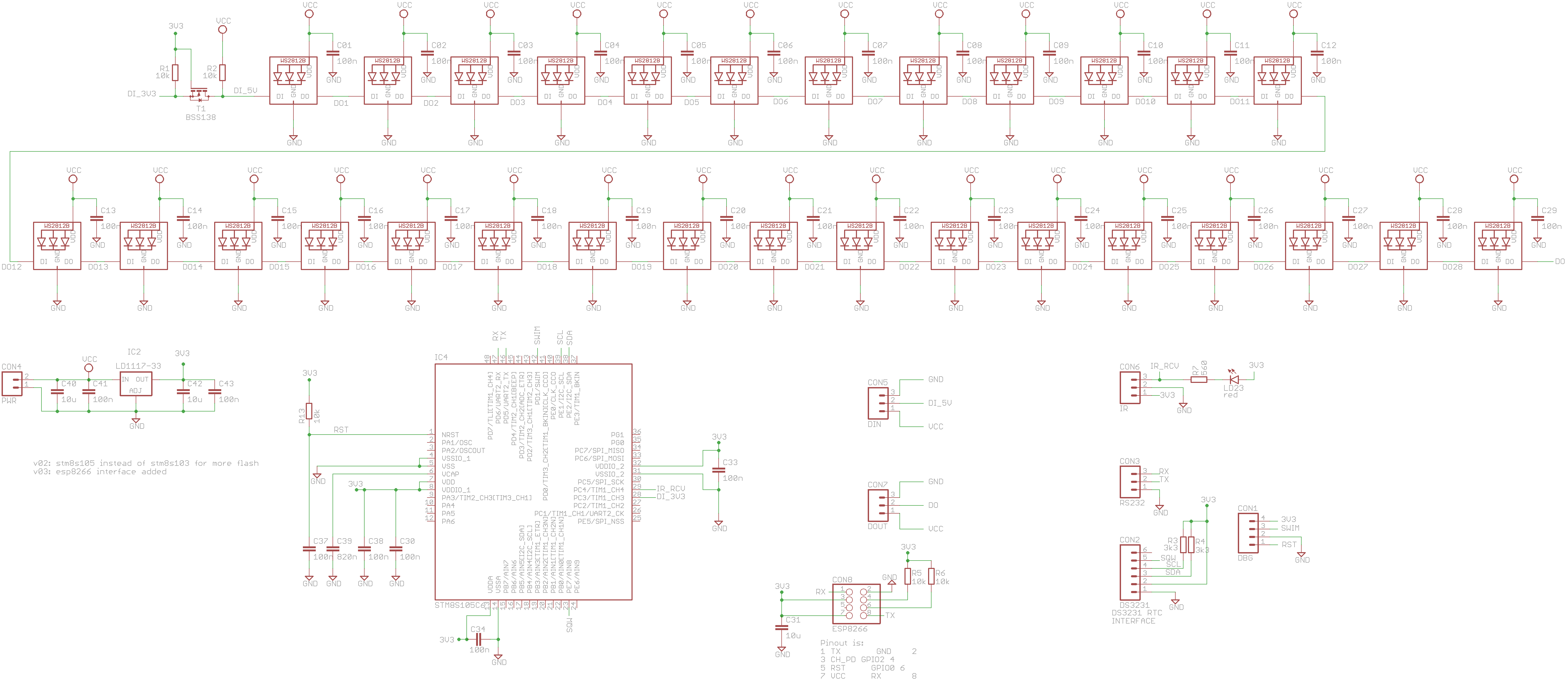
- 6 x 29 WS2812B leds: 6 digits, 4 leds/segment, 1 decimal-point
- 6 PCBs (daisy-chain) are needed for time-display
- STM8S105C6T6 uC with 32K Flash, 2K RAM and 1024 bytes EEPROM
- IR (TL1838) receiver with led indication
- DS3231 Real-Time Clock (RTC)
- SWIM debug interface
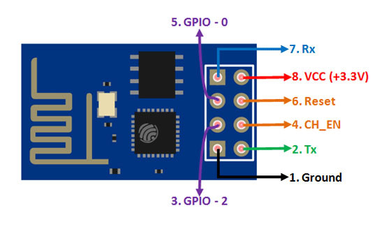
- ESP8266 interface for reading date and time from NTP time-server
- 1 = Show version number of current firmware
- 2 = Show status of last ESP8266 update. Time is retrieved from ESP8266 every 12 hours. Display shows "txxx y" with xxx the remaining time in minutes until a next update to the ESP8266 NTP server, y is the status from the last update: 0 (red) for error and 1 (green) for a successful update.
- 3 = Get Date and Time from ESP8266 NTP Server and update DS3231 RTC. Displays shows time in white for a second if successful.
- 4 = Show temperature for 5 seconds.
- 5 = Set intensity of colors (01 - 39). Use Up, Down, Ok, 0-9 to set a digit.
- 6 = Invert blanking active/not-active signal (on=off, off=on) for 60 seconds.
- 7 = Test mode for 60 seconds.
- 8 = Set Blanking-begin time. Use Up, Down, Left, Right, Ok, 0-9 to set a digit.
- 9 = Set Blanking-end time. Use Up, Down, Left, Right, Ok, 0-9 to set a digit.
- # = Show date & year for 8 seconds.
IAR development environment for STM8
- Arduino 1.8.15 IDE with board "Generic ESP8266 Module"
- Connect GPIO_0 to GND for programming, to VCC for normal booting
- Connect GPIO_2 to VCC, leave RESET open and CH_PD to VCC.
- Connect Vcc to +3.3V
- Connect TX to RX and RX to TX of UART-adapter
- Use file esp8266_ntp_server.ino

