https://www.hackster.io/Edoliver/coolbreaker-automotive-smart-circuit-breaker-and-switch-d4b7d0
Automotive Smart Circuit breaker and switch to increase efficiency in your car's electrical system and prevent electrical hazards.

Hardware components
- CoolMOS C7 Gold SJ MOSFET
- Infineon CoolMOS C7 Gold SJ MOSFET× 1
- Custom PCB
- Adafruit Feather HUZZAH with ESP32× 1
- Infineon EiceDriver x1
- Capacitor 100 nF
- Capacitor 10 µF
- 10R Resistor
- 3R3 Resistor
- DFRobot ACS758 Current Sensor board
Software apps and online services
- Autodesk Eagle
- Fusion 360
- Autodesk Fusion 360
CoolBreaker: Automotive Smart Circuit breaker, battery protection and switch.
For several years now the automotive industry have relied on car fuses as they are cheap and easily changeable. Most cars have a fuse box that looks like this in order to manage their electrical system:

Even Teslas use a fuse box when dealing with Accesory wiring and internal electrical systems:
https://www.carcarekiosk.com/video/2017_Tesla_S_90D_Electric/fuse_interior/replace
Ordinary car fuses generally used in most applications have several drawbacks and they can be inefficient in case of a short circuit or with faulty electrical systems. If you don't believe me, let's ask motoforlife:
https://www.youtube.com/watch?v=sIqoVgxmnvQ
Nowadays we have cars with a lot of accesories. Lights, USB ports that in turn power more devices, audio systems, even refrigerators in some trucks and more. And we want even more stuff.
But, what do we have in hand for electrical automotive protection?
1.- More Fuses (with all their drawbacks).
2.- Mechanical and electromechanical Circuit breakers.
3.- Relay harnesses.
Lets analyze both options:

Relays are everywhere in a car, and they are seldom solid state ones.
Well, fuses are just like the ones we used to have at homes or in home appliances. As a current above their limit passes through the wire, it melts it breaking it and thus the circuit. There's a huge reason we have already moved on from those in relation to home use as they are unreliable and almost dangerous in some aspects. Yes, the automotive industry uses them because they are cheap and easily changeable, but in order to find a fault you have to go in with a multimeter still and find it by hand like in the following video:
https://www.youtube.com/watch?v=n5FJDgcdii8
As you can see these kind of systems do little to automatically find problems related to batteries dying, and the most expensive part of the electrical system is, you guessed it, the battery. And they can be faulty with time, as shown in the video.
The second alternative is a circuitbreaker, but in automotive terms what you can get is one of these: https://www.youtube.com/watch?v=vA1cz021OvU
That is just using again the thermal properties of the metal inside to break the circuit. They are also prone to failing and if there's rattling or movement they are unreliable.
Until very recently there were few alternatives to electromechanical and magnetic circuit breakers. They have undesirable characteristics such as arcing and switch bounce (with corresponding noise and wear), while accomodating large unwieldly packages in their high power systems.
Racing and rally cars are already moving on from these kind of solutions as they both expect heavy usage, rattling, noise, and sometimes they need to kill the battery (because of fires and explosions) so they use solid state solutions for those, even remote ones.
Even aircraft has improved their capabilities with solid state solutions such as: http://verticalpower.com
There is no other option easily attainable in the market nowadays....let's try building one.
Enter CoolBreaker the Solid State Circuit Breaker using the extremely impressive CoolMOS 600 C7 from Infineon.
If you are going to replicate this experiment please use every security measure possible, DC energy is much safer that AC but still when managing these currents accidents can happen.
Solid state technology applied to this traditional device has resulted in circuit breakers free from arcing and switch bounce, that offer correspondingly higher reliability and longer lifetimes as well as faster switching times. A typical solid state circuit breaker will switch in a matter of microseconds, as opposed to milliseconds or even seconds for a mechanical version. New solid state products currently on the market utilize the many benefits associated with power MOSFETs to deliver aproduct far superior to earlier silicon versions. PowerMOSFETs offer low on resistances (as compared to bipolar transistors), low voltage drops, low EMI, faster switching times and good thermal stability of key parameters. And we have the latest technology in the CoolMOS C7 provided by infineon.
Now to the fun part.
What do we want in the product?
For it to be reliable, the switching times of the CoolMOS provides us that. Cheap in comparison with fuses and mechanical circuit breakers and Relays. If we use a MOSFET driver and the CoolMOS we can achieve that with a simple circuit. We might want to know of any parasitic currents that are draining the battery. Hall efect sensor? Yeah let's go with a Hall effect sensor. For it to be smart. We want to know exactly which accesory is short circuiting. You saw this coming in the era of IoT. This will increase the base price but for this prototype, it'll be fun. It has to be small enough (taking into consideration that we can just build a PCB instead of a panel this will be easy to achieve). A solid state solution for this will actually be leaps and bounds better than the previous ones as it'll be imprevious to water, weather, grime, oxidation, tough environments, rattling and all the problems that we find in fuses and electromechanical solutions.
We have to take into consideration that this will be an auxiliary to the PDU for the accesories. Powering up a vehicle requires between 250 and 1000 amps for a cold start so it is quite difficult to do just with silicon. This product will be able to protect your accesories, your battery and will increment its electrical efficiency enourmously.
Instead of fitting everything into a small pcb and lets say controlling everything via an ATTiny, I want this proyect to be easily doable for any maker at home without having to order expensive PCB that he may not be able to solder, so everything will be done in a modular fashion.
We will be using:
A hall effect sensor module based on the ACS758 which is a very reliable and robust sensor.


First I began designing the PCB as the CoolMOS provided by Infineon came in, is SMD version on a HSOF package.
The main goal for this module is to create a PCB that can be attached via headers to any other contraption that the community might want to design later. YES, the module by itself is marketable as it provides an easy way for makers and hobbyists to come up with new solutions.
This is a community of makers in the end so a module with the CoolMOS and its Driver was the way to go.
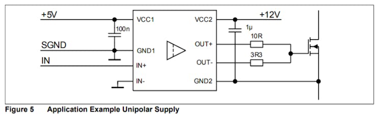
The proper driver for the CoolMOS is the 1EDI60N12AF EiceDRIVER by Infineon. In order to create the module first I went to its Datasheet and according to its characteristics I decided on following up with this design, you have to choose the resistors according to your application(see this application note:https://www.infineon.com/dgdl/Infineon-EiceDRIVER-Gate+resistor+for+power+devices-AN-v01_00-EN.pdf?fileId=5546d462518ffd8501523ee694b74f18), for mine this one sufficed.:
Then checking the CoolMOS' datasheet I found that it has a special pin for the driver. Very Interesting.

Then according to the guide of use in the official site of the driver I followed through and designed the following schematic:

As you can see the intention is to use pinheaders on one side for the logic part and Screw terminals for the power side. With this we separate power from logic and protect our microcontrollers accordingly (And those expensive Bluetooth boards!). Number 1 on the screw terminals goes to the load, that in this case will be a Halogen lamp but can be whatever.
Here is a picture of the Gerber files before being sent to be made:

As you can see I went for big clearance and width as it is a power application, and to prevent any problem during manufacturing.
After a while they arrived!


And the soldering process began. It was arduous but relaxing as I forgot to buy solder paste, nevertheless you can see the process in the build video.
Here is the result:

Now its time to go full circle and create the full product by joining the boards together. But first, time to test everything in the lab!
Here is the building process with a little narration:
https://www.youtube.com/watch?v=XJemC6Y_ZpY
Here is the schematic of the modules joined together:

As you can see we have the Adafruit Huzzah ESP32 for the logic and to switch the MOSFET via its driver. Tied to that we have the hall sensor to detect when the Current passes the threshold and break the circuit by swithching the MOSFET.
To know the current we have to set the Hall sensor to the Feather logic.
I know what you are saying: Ohhh but Edoliver the Feather ESP32 works on 3.3V logic!
Yeah I know, for that I set up a voltage divider with these characteristics:

Just grab Vin from the USB supply pin and from the middle grab that A0.
Now we have to make a Blynk app and upload the Code to the Feather HUZZAH (Code at the end). Blynk allow us to develop very fast IoT applications, remember when using the widgets to select the proper pins that you want to track. For every new app that you make in Blynk you should get an authentication number. You just have to download the app, set an account and you are set as there are countless examples of Arduino IDE sketches.
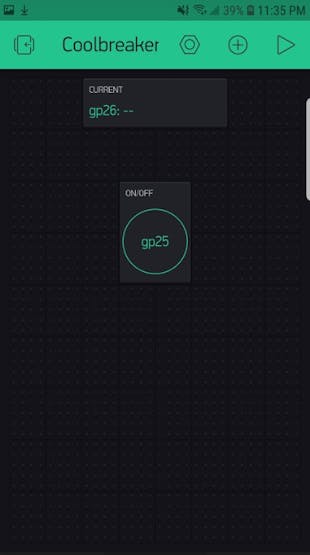
The intention of the app is to have reset capabilities at all times or shutdown the load whenever we need to.
At the same time whenever the current passes the threshold we setup in the code it switches the MOSFET to off.
readings[index1] = analogRead(A0); //Raw data reading
readings[index1] = (readings[index1]-2048)*3.3/4096/0.04+5.04;//Data processing:510-raw data from analogRead when the input is 0; 5-5v; the first 0.04-0.04V/A(sensitivity); the second 0.04-offset val;
total= total + readings[index1];
index1 = index1 + 1;
if (index1 >= numReadings)
index1= 0;
average = total/numReadings; //Smoothing algorithm (http://www.arduino.cc/en/Tutorial/Smoothing)
currentValue= average;
Serial.println(currentValue);
if (currentValue > 5) digitalWrite(LED_BUILTIN, LOW);
This is the most important part of the code as you can see it reads the Analog pin A0 and sets a value for the current, if that value is bigger than the set threshold that in this case is 5 amps then the MOSFET is turned off.
I know what you are saying: Ohhh but Edoliver the Feather ESP32 works on 3.3V logic!
Testing and Showcase!
https://www.youtube.com/watch?v=gUYDCipCUN8
So we have a tentative module for 13 Dollar aproximatelly.
It protects from overcurrents It stops the battery from draining if there are still parasitic currents. It is smart as it can be controlled from your phone. It is solid state so any rattling or mechanical parts will not prevent it from functioning correctly. Provides quicker intervention time, less maintenance, less footprint and more safety. If we compare it with:
These are only fuses and are much more expensive.
And Relay harnesses are about the same but with the known problems:
Adding the Bluetooth functionalities the prize increases by 5 dollars but there is nothing in the market quite like it. And if we compare it to some of the best circuit breakers in the market the prize is very competitive.
- For the future rollout, I might expand to control the current at which the circuit will break via bluetooth in order to fit every car accessory.
Thank you for reading along!
References: Took huge inspiration from Electroboom and Great Scott's youtube channels:
https://www.youtube.com/user/msadaghd
https://www.youtube.com/user/greatscottlab
Circuit heavily based on the following paper:
https://www.eeweb.com/app-notes/solid-state-circuit-breaker
If you want to go deep into the rabbit hole of automotive electrical systems:
https://www.reddit.com/r/askscience/comments/lfwj7/why_do_cars_have_fuses_and_not_breakers/
https://news.ycombinator.com/item?id=8869221
https://www.e46fanatics.com/forum/showthread.php?t=627979
https://www.quora.com/Why-do-cars-uses-fuses-rather-than-circuit-breakers
https://www.consumerreports.org/hybrids-evs/electric-cars-101-the-answers-to-all-your-ev-questions/
https://www.infineon.com/cms/en/product/power/gate-driver-ics/1edi60n12af/?intc=reco#
https://learn.adafruit.com/adafruit-huzzah32-esp32-feather/pinouts