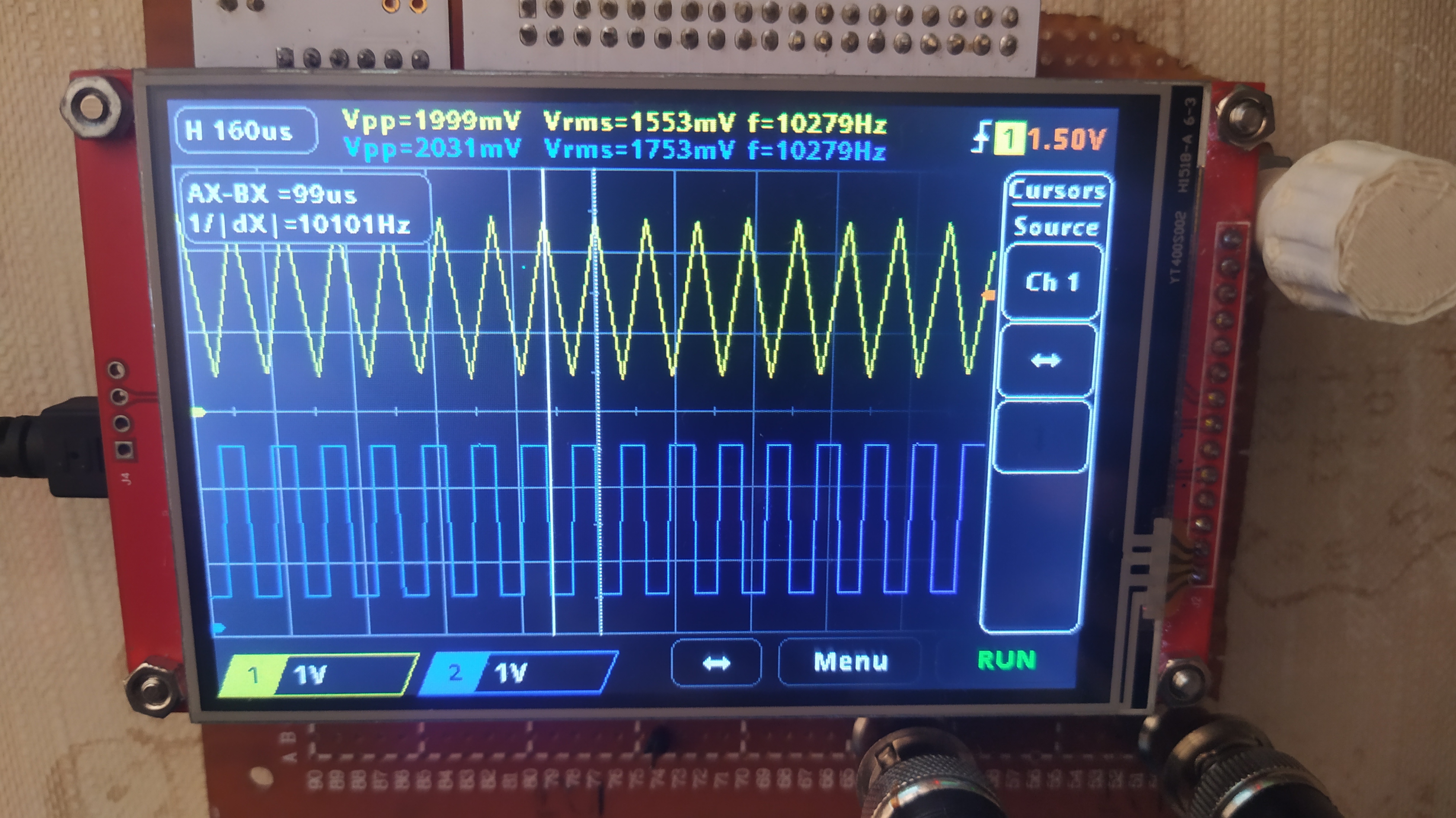
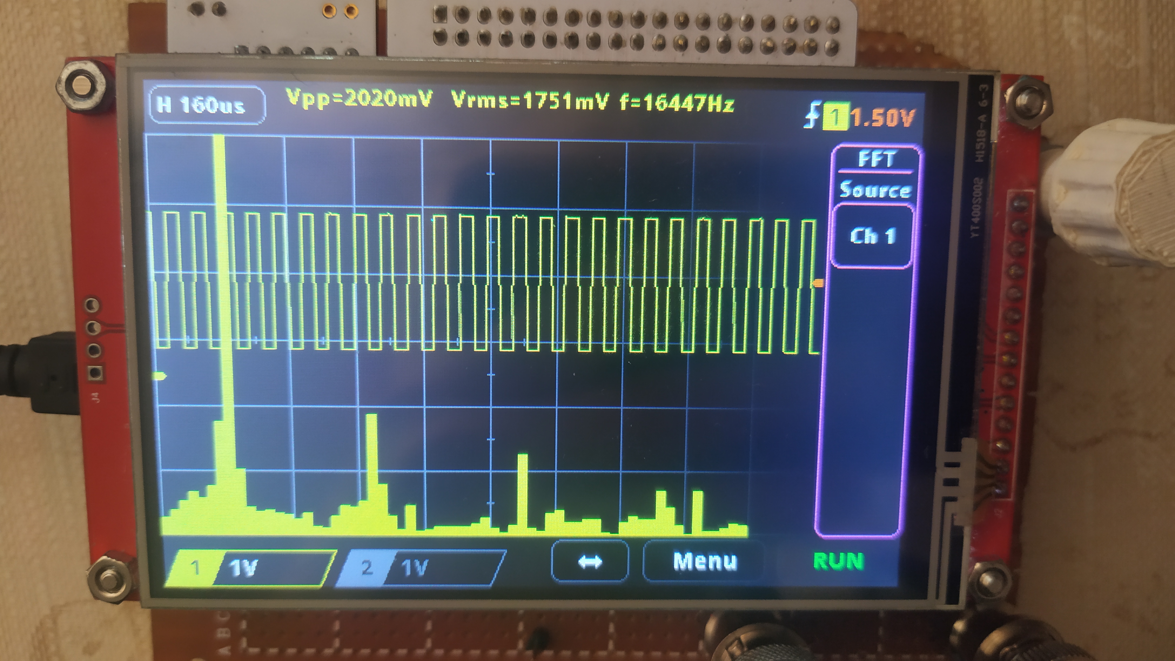
This project is a simple oscilloscope built using an STML476RG microcontroller and a 4" TFT SPI 480x320px V2.1 LCD with an integrated ILI9488 driver and touchscreen with an XPT2046 driver. It was developed for the Robot Controllers project during the 6th semester of AiR at PWR.
- 2 channels
- FFT (Fast Fourier Transform)
- RMS, peak-to-peak, and frequency measurements
- Horizontal and vertical cursors
- Auto mode trigger (channel 1)
-
LCD
STM pin Component pin Signal description PA6 SDO(MISO) TFT_MISO PC9 LED TFT_Backlight PB3 SCK TFT_SCK PA7 SDI(MOSI) TFT_MOSI PC4 DC/RS TFT_DC/RS PA10 RESET TFT_RESET PC8 CS TFT_CS -
Touchscreen
STM pin Component pin Signal description ----- T_IRQ T_IRQ PC2 T_DO Touch_MISO PC3 T_DIN Touch_MOSI PB12 T_CS Touch_CS PB10 T_CLK Touch_SCK -
Rotary encoder
STM pin Component pin PA9 ENC_A PA8 ENC_B PC0 ENC_BTN -
Oscilloscope channels
STM pin Component pin Signal description PC5 BNC connector 1 Channel 1 PB1 BNC connector 2 Channel 2 -
Test signal output
STM pin Component pin Signal description PB0 GEN OUT connector 1kHz test signal
- Navigate to the file
oscilloscope.cand locate line 35. Remove the comment slashes (//) to activate the functiontouchScreenCalibration();. Save the changes and upload the code to the device. - Open a Serial monitor on your PC. You should observe the following prompt:
Press the screen at the yellow squares that appear, then paste the following line into stm32_adafruit_ts.h : - Interact with the LCD screen by pressing on the three yellow squares. Upon completion, the calibration values will be displayed. For example:
#define TS_CINDEX {1777297, 4469, -237569, 908499464, -171651, 9601, 587895710} - Follow the instructions provided in the previous step by copying and pasting the displayed line into the file stm32_adafruit_ts.h. After pasting, comment out line 35 in
oscilloscope.c, and re-upload the modified code to the device.
- Touchscreen Library: stm32_hal_graphics_display_drivers - This library was chosen for its effective calibration function and reliable touch detection.
- LCD Library: ILI9488-DMA-SPI-STM32 - This library was selected for its high display speed. It was modified to use a frame buffer to prevent flickering.
(No need to install any libraries; the appropriate files are included in the project.)
Special thanks to Eryk Możdzeń, who helped with programming.


