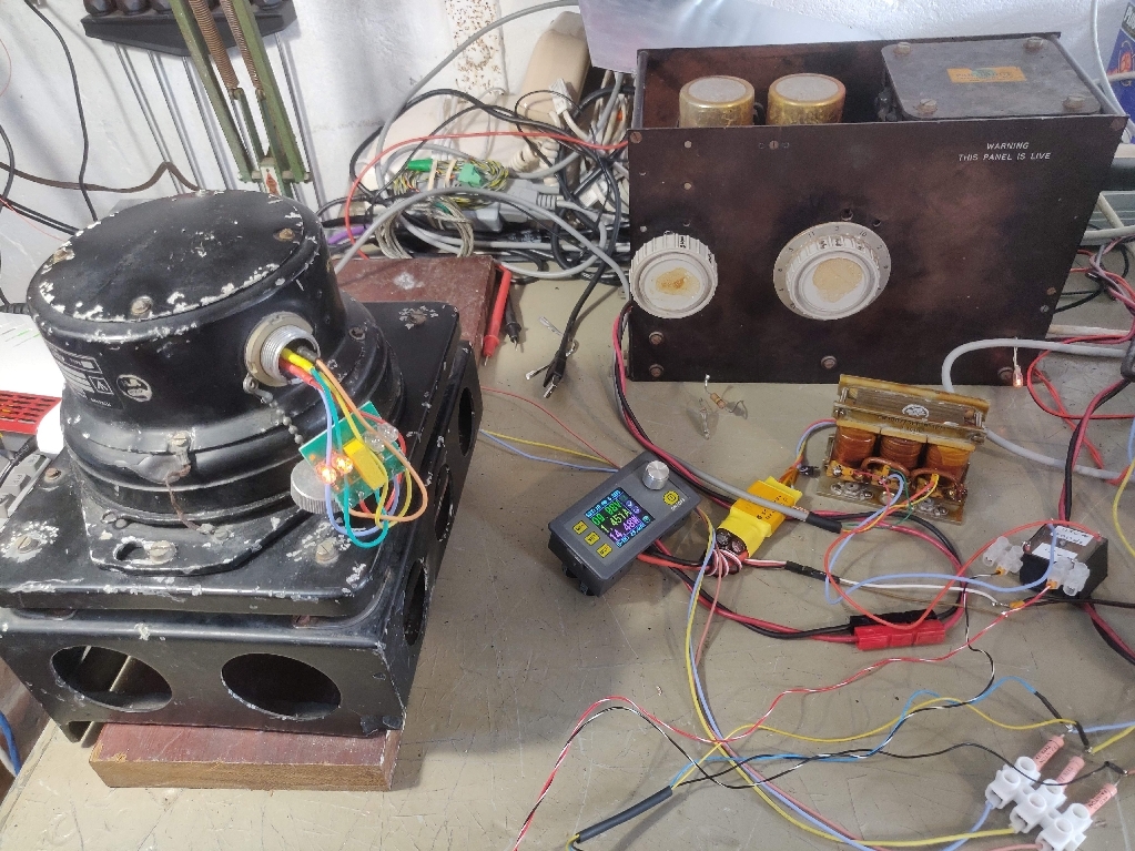
Provides a reference from which the angular movement of an aircraft can be measured. The output signal is derived from a thre line synchro transmitter (90 V. line).
- Gyro synchro output test on turntable
- 115 V, 400 Hz
- Phase rotation A,B,C
- Phase B earthed
| Pin(12) | Function |
|---|---|
| A | Monitor |
| B | Monitor |
| C | Monitor Common |
| D | Synchro |
| E | Synchro |
| F | SYnchro |
| G | n/c |
| H | Phase-A |
| J | Phase-B |
| K | Phase-C |
| L | n/c |
| M | Link to J |
| Pin(12) | Pin(6) | Colour | Name |
|---|---|---|---|
| H | A | Red | Phase-A |
| J | B | Green | Phase-B |
| K | C | Blue | Common-C |
| - | D | Yellow | Test |
| - | E | Orange | Test |
| - | F | None | n/a |
-
Timelapse video showing drift drift
-
Timelapse video showing monitor adjustments monitor
-
Realtime video showing erect test outputs erect
-
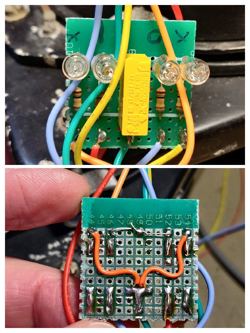
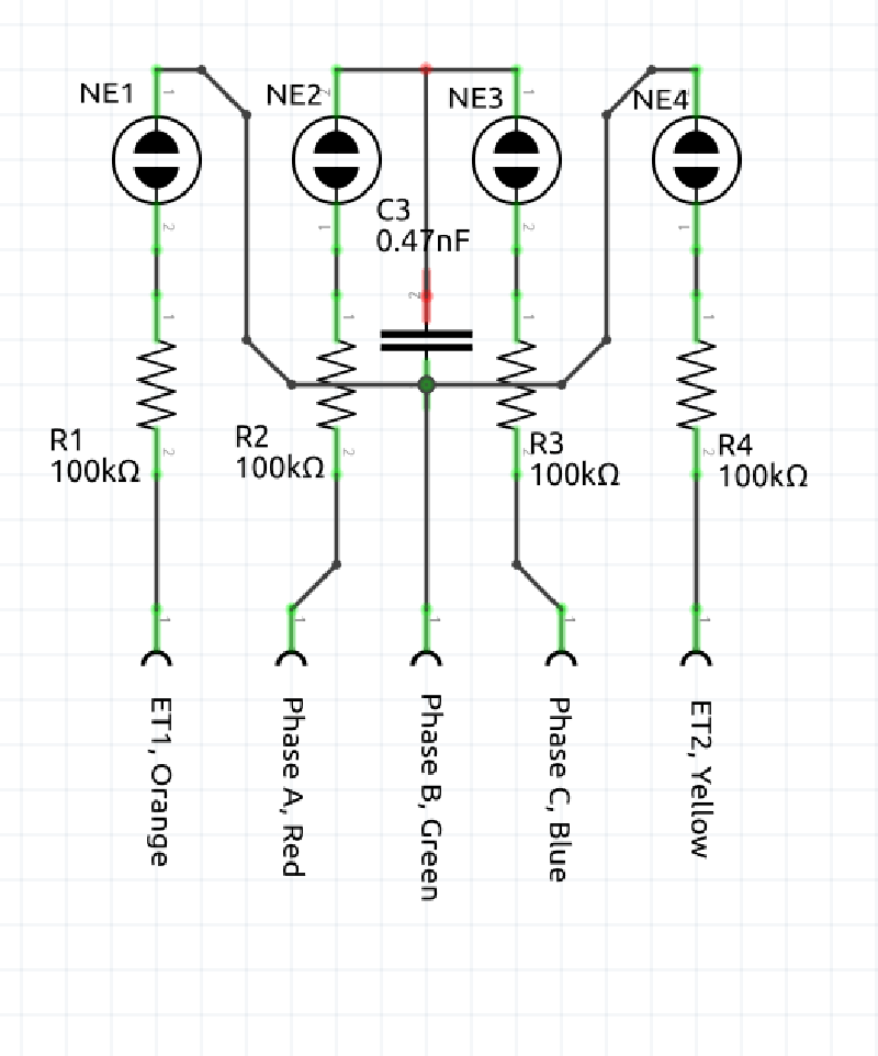
Outer two neons are erection test lamps, should flash on from time to time.
-
Inner neons, One conected to red wire should be lit, One connected to blue wire should be off. Phase missing or rotation error otherwise.
| Rotation | NE2 | NE3 |
|---|---|---|
| A-B-C | On | Off |
| B-A-C | Off | On |
| Erection | NE1 | NE4 |
|---|---|---|
| Steady | Off | Off |
| Right | On | Off |
| Left | Off | On |


