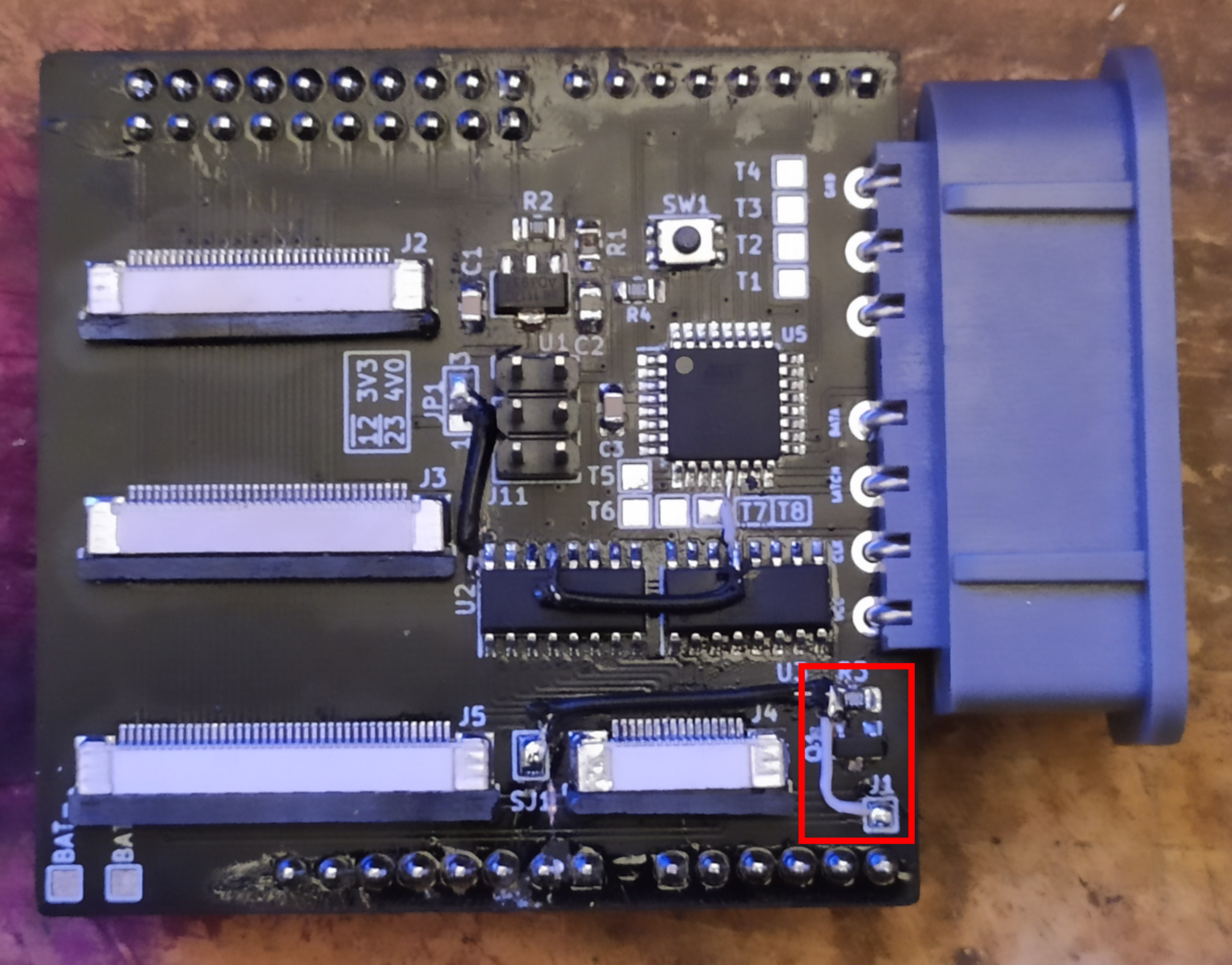
This is a shield for the gbaHD project.
Has the following features.
- Connects via female headers to the Edge board (shield)
- Has a FFC 40 pin connector for OGBA LCD connector. Need Type-B Cable (Reverse) vvv=======^^^
- Has a FFC 32 pin connector for OGBA LCD connector. Need Type-B Cable (Reverse) vvv=======^^^
- Has a FFC 34 pin connector for GBA-SP LCD connector. Need Type-A Cable (Direct) vvv=======vvv
- Has a FFC 16 pin connector for controls with a wire up board. Need Type-B Cable (Reverse) vvv=======^^^
- Has a ATMEGA328p for using a SNES connector to control the GBA.
- Has a high-side switch for GBA power controls (IGR).
- Has eight (8) testpoints on the bottom side for future features.
- no known issues
If you wish to contribute, see something wrong or want to add a feature please make a pull request or leave an issue!
| Reference | Value |
|---|---|
| C1, C3 | 100nF 0805 |
| C2 | 22uF 0805 |
| R1 | 2.2K 0805 |
| R2 | 1K 0805 |
| R3, R4 | 10K 0805 |
| U1 | LM1117F-adj SOT89-3 |
| U2,U3 | 74HC595 SOIC-16 |
| U4 | SNES 7Pin |
| U5 | ATMEGA328p-AU |
| SW1 | XKB-TS-1185EC-C-D-B |
| J2 | JUSHUO AFC07-S32FCC-00 |
| J3 | JUSHUO AFC07-S34FCC-00 |
| J4 | JUSHUO_AFC07-S16FCC-00 |
| J5 | JUSHUO AFC07-S40FCC-00 |
| J6 | PinHeader 1x6 2.54mm |
| J7, J9 | PinHeader 1x8 2.54mm |
| J8, J10 | PinHeader 1x10 2.54mm |
| J11 | PinHeader 2x03 2.54mm |
| Q1 | SI2301DS P-Chan MOSFET SOT23 |
In order to program the MCU, you need an arduino to use as ISP.
Use the following image to wire up an arduino to the board to program it.
I would also recomend programming while it's not seated in the FPGA board.
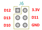
After wiring the board, follow this tutorial to flash the the sketch to the board.
ICSP Tutorial
As target board choose "Arduino Pro or Pro Mini - ATmega328p - 8MHz"
Fuses must be Low: 0xE2 High: 0xD9 Ext: 0xFF
As the OGBA and the GBA-SP use different battery technologies, they also require different voltages.
The OGBA needs approx. 3V (2x 1.5V from AA cells - 3.3 will also fit) and the GBA-SP needs 3.3 - 4.2V (Lithium battery - 4.0V will also fit).
Therefore we have a solder-jumper (JP1) which we use to choose between 3.3V and 4.0V.
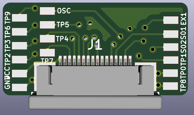
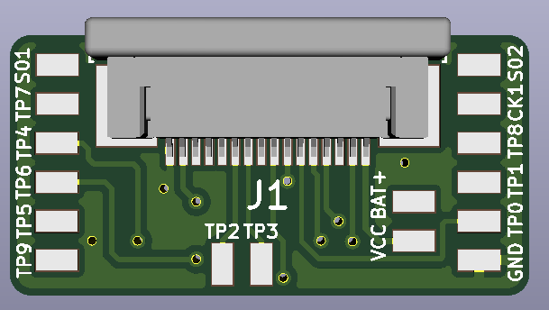
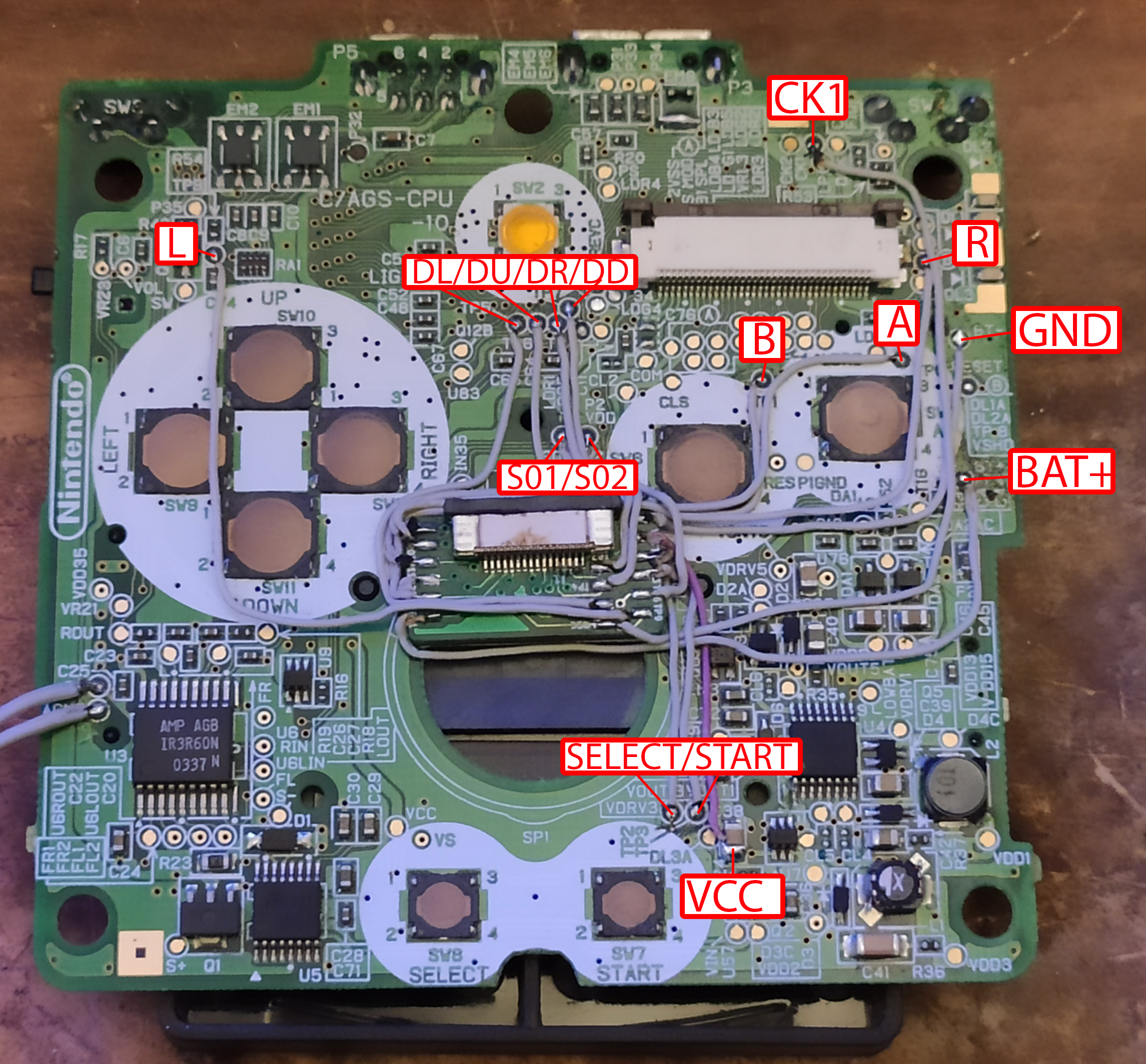
Plus we need to solder-bridge J1 and J12 due to the fact, that the power-managing chip on the SP mainboard blocks the power on if it detected a
low battery recently. This will replace the power switch which therefore needs to be in off position always!
v20210406 Owners If you want to use this board with an SP simply connect the J1 to the VCC-line on the shield and on the mainboard connect EX1 with BAT+ and VCC with VCC.
