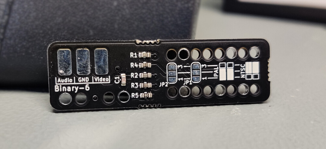
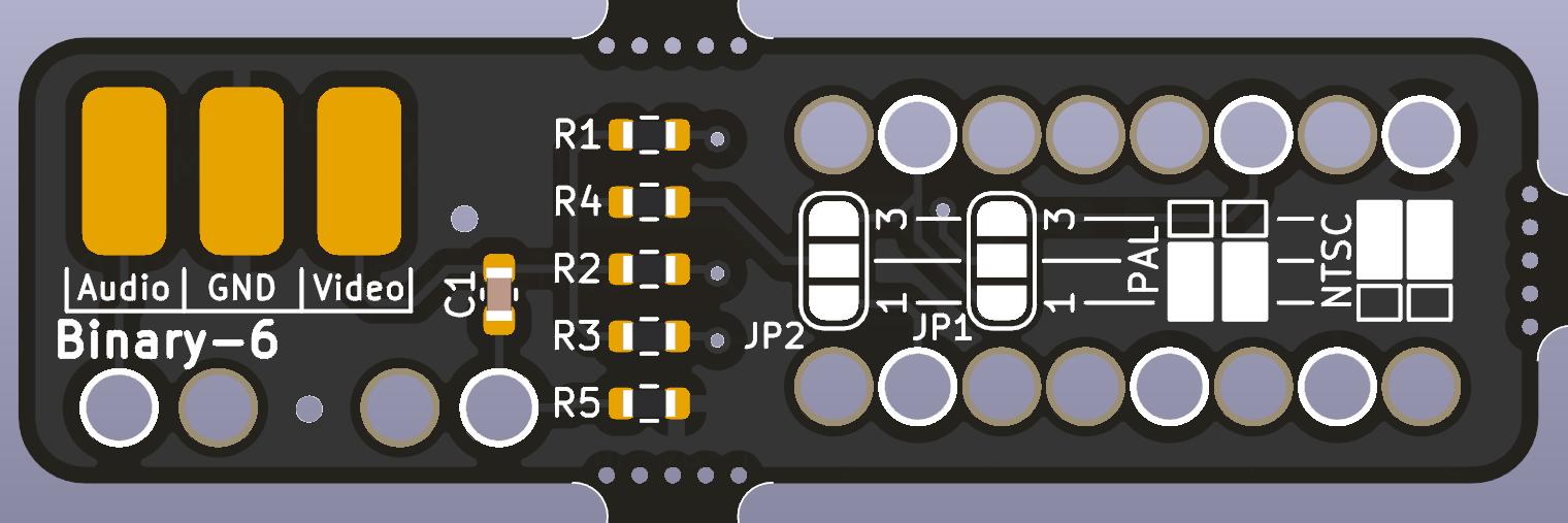
This is a single board solution to mod Atari 2600 Junior consoles, which normally only use RF outputs, into outputting composite AV.
Analog RF isn't typically found on most modern TVs anymore, and even composite AV is fading out, but it is still fairly easy to hook up on most systems.
This mod in general isn't anything new, it has been for literal decades but usually it was done with free floating wires and components. This PCB aims to make installation a lot easier.
All files to manufacture your own boards are uploaded in the production files directory, but for your convenience, finished boards are also stocked at Tindie.
If you like my work please consider supporting my caffeine addiction!
This mod is compatible to PAL and NTSC versions, configurable via jumpers.
Please make sure your Junior board mechanically looks like the one shown in the installation guide below. There are some revisions, namely Rev D boards, that are mechanically different in the lower left corner where the mod is supposed to be placed, that prevent the PCB from slotting in.
This installation guide was done on a PAL Rev C Junior board.
- AV Modchip
- Audio / Video ports of your liking (RCA for example)
- Screened wire (Stereo audio cable works well)
- Soldering iron
- Screwdrivers / Pliers
- 30 Minutes of time
The case gets flipped on its face and 5 screws will be removed. On the front you will find some clips that need to be carefully opened as well. The old plastic likes to break easily.
The metal panel has multiple bent tabs around the perimiter that need to be bent straight again to take the panel off.
In the lower left hand corner there is the backside of the CD4050 IC. Place the modchip according to the picture. It will fit over all pins in the area. There are 7 contacted holes that need to be soldered in. This will connect all video as well as audio signals to the modboard. Sometimes you are required to bend some pins up with a screwdriver if the chip does not fit perfectly.
You will need to set JP1 and JP2 according to your system. Both jumpers need to be connected MIDDLE-DOWN (1-2) for PAL systems, or MIDDLE-UP (2-1) for NTSC systems.
If you fail to connect any jumpers, you will not get any usable video out of your system, but nothing will break.
In this guide, Both jumpers were set MIDDLE-DOWN since I am using a PAL system.
The top left corner of the chip has contacts for audio and video, in my case:
- Screening – GND
- Red – Audio
- White – Video
I wired up a triple RCA jack here, putting the audio signal on both center pins of the red and white jack for left and right audio, the video signal onto the center pin of the yellow jack, and GND on the outer ring of all three
After routing the wires you can put the screening panel back on and bend the metal tabs back into place
This is what the ports could look like. Of course you don’t have to put the jacks as crooked as I did.
All files to manufacture your own boards are uploaded in the production files directory, but for your convenience, finished boards are also stocked at Tindie.
The production files were created with JLCPCB in mind. The BOM and Gerbers specifically fit their requirements to have the full PCB panel including PCBA assembly manufactured with them. Alternatively, in the BOM you will find LCSC part numbers to buy the parts at LCSC individually.
The initial version was never published open source, but has been added here for legacy documentation purposes.
It was originally done in EAGLE but imported into KiCad. No fabrication files are provided and the files are not imported perfectly. The manual still references this version of the board, as the general installation procedure did not really change.
The old version was only compatible to PAL systems, while the new board released here also works on NTSC systems, as long as your Atari junior board revision fits mechanically.
- Differences between PAL and NTSC PCBs by were documented in AtariAge forums.
- Ancient version was first published and documented in CircuitBoard forums, referencing an original tutorial in the same forum.
This work is licensed under a Creative Commons Attribution-NonCommercial-ShareAlike 4.0 International License.


