This sketch is for the RP2040 Arduino Nano Connect connected to a 320 x 240 TFT display. It uses the onboard microphone to sample audio signals and display the frequency spectra on a TFT display. The sketch uses FFT analysis to extract the frequency spectrum from the signal.
A similar sketch that samples an ADC channel instead of a PDM microphone can be found here.
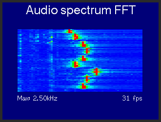
The spectrum can be displayed as a spectrum (frequency .v. amplitude) format, or as a scrolling waterfall (frequency .v. time).
The peaks are displayed and decay. The waveform can also be displayed.
Screen update rate varies with the number of FFT samples taken, example fps performance with 62.5MHz SPI clock:
- FFT samples = 64 -> 81 fps
- FFT samples = 128 -> 78 fps
- FFT samples = 256 -> 54 fps
- FFT samples = 512 -> 21 fps
The FFT display area is set to 256 x 160, this could be changed. The width should be an integer multiple of samples/2 where that integer is a minimum of 1.
The maximum fps will depend on a number of factors:
- The number of FFT samples, higher numbers take more time
- The sample rate (default is 14kHz), higher rates reduce time taken and change frequency display scale
- The time it takes to gather the N samples (sample rate/N fps)
- The time it takes to update the screen (depends on sprite size and write speed)
The displayed frequency span is sample rate/4 (so default range is 0-3.5kHz).
Note: Some Arduino Nano Connect PDM microphones do not work at certain sample rates (mine does not work at 16kHz).
There are #define options to alter the defaults:
- Sample rate
- FFT sample count
- FFT display area size
- Peak marker on/off and decay rate
- Peak marker as bar or dot
- Frequency amplitude gain
- Oscilloscope trace on/off and amplitude gain
- Waterfall option (default off)
The display update uses DMA so that the display can be updated while an FFT and sample gathering is in progress.
To stabilise the 'scope trace the sketch uses a simple method to determine a rising edge trigger point.
The sketch requires the Earle Philhower RP2040 board package (includes PDM microphone library) to be used: https://github.com/earlephilhower/arduino-pico
The TFT_eSPI library is also used, available using the Arduino IDE library manager or here: https://github.com/Bodmer/TFT_eSPI
Screen shots: