![]()
![]()
![]()
Example to show that it is possible to use Logisim Evolution to create chip layouts for TinyTapeout.
This example implements the following circuit:
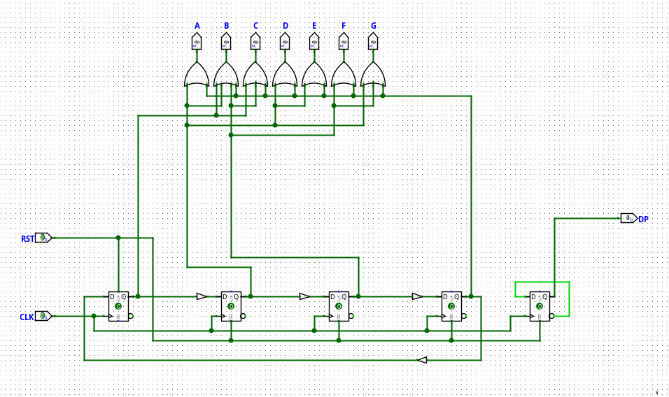
All it does is flash the number sequence "1 2 4 8" on the 7-segment display, while blinking the DP.
After exporting the project from Logisim as Verilog, only a few lines of code need to be modified on the export to make it usable with TinyTapeout.
Firstly, export your Logisim Evolution project as Verilog. It’ll ask you to choose an FPGA board and assign a pinout. Choose whatever, and randomly assign the pins. It doesn’t matter. This only determines values in a config file you won’t be using. You’re only interested in the Verilog. On that note, select "Verilog" as the export language in the Settings.
Go to the path the files were exported to. The log in the export dialog should show you where they are. Find the 'verilog' directory, and copy everything in there into the 'src' of your TinyTapeout repository.
Next, you need to edit the top level module definition to look like what TinyTapeout expects. Open the 'toplevel/logisimTopLevelShell.v' file in a text editor or IDE of your choosing. You will be changing most of this.
Firstly, the module definition. By default, it will look something like this:
module logisimTopLevelShell( A,
                             B,
                             C,
                             D,
                             E,
                             F,
                             G,
                             DP,
                             n_CLK_0,
                             n_RST_0 );
As you can see, Logisim names all of the inputs and outputs for you. Usually, this would be a good thing. But in this case, it is not. TinyTapeout expects the module definition to look a very specific way. So, replace it entirely with this one:
module module_name(
  input [7:0] io_in,
  output [7:0] io_out
);
This is also a good time to change the module name to one you like. [github username]_[project name] is the recommended way to do it. But now the I/O definitions are gone. So you need to create wires for the named I/Os below, and assign them to elements of io_in or io_out.
Below the module definition, you will see several blocks. Take note of the block of wire definitions. This is the one you want to keep. Everything in here that isn’t the wire definitions or the connection to the top level circuit component at the end needs to go. Delete the input, output and assign blocks.
Your config should now look like this:
module module_name(
  input [7:0] io_in,
  output [7:0] io_out
);
   wire s_CLK;
   wire s_A;
   wire s_B;
   wire s_C;
   wire s_D;
   wire s_E;
   wire s_F;
   wire s_G;
   wire s_DP;
   wire s_RST;

   main   CIRCUIT_0 (.CLK(s_CLK),
                     .A(s_A),
                     .B(s_B),
                     .C(s_C),
                     .D(s_D),
                     .E(s_E),
                     .F(s_F),
                     .G(s_G),
                     .DP(s_DP),
                     .RST(s_RST));
endmodule
Now, you will need to assign the wires to the inputs and outputs. For all inputs, do the following:
Go to the wire definition for that input. For example, wire s_RST. Then, set it equal to an index of io_in. For instance, wire s_RST = io_in[1];. This will make s_RST be connected to the second of your chip’s 8 inputs.
For all outputs, do the following:
You will need to add a new line assigning to an index of io_out the value of one of the wires. For instance, to connect s_A to output pin 1 on the chip, write: assign io_out[0] = s_A;
Your final config should look like the one in this repository.
You’re almost done. Last thing to do is to list all the verilog source files in your info.yaml. Open that file and right at the top, under source_files, expand that list to include every .v file exported by Logisim. There might be quite a few, so make sure not to miss any. Of course, don’t forget to fill in all the other info as well.
And that’s it. Your project should now be build-ready. So push to the repo, and watch the actions pipeline build your design.
And the best part: you only need to do this once! The logisimTopLevelShell.v file does not change between exports, unless you change the names of your I/O pins! Just make sure to not overwrite this file the next time you copy in a updated logisim export, and you’re good to go!