This is my attempt to the Assessment Task - 1 (also described below) of QOSF's Quantum Computing Mentorship Program Cohort 4.
Thanks to @qosf and Michał Stęchły for accepting this attempt as one of the model solutions to the task!
Please view this page in light mode to be able to see the latex expressions better
Design a quantum circuit that considers as input the following vector of integers numbers:
[1,5,7,10]
returns a quantum state which is a superposition of indices of the target solution, obtaining in the output the indices of the inputs where two adjacent bits will always have different values.
In this case the output should be: , as the correct indices are 1 and 3.
1 = 0001
5 = 0101
7 = 0111
10 = 1010
The method to follow for this task is to start from an array of integers as input, pass them to a binary representation and you need to find those integers whose binary representation is such that two adjacent bits are different. Once you have found those integers, you must output a superposition of states where each state is a binary representation of the indices of those integers.
The key to this task is to use the superposition offered by quantum computing to load all the values of the input array on a single quantum state, and then locate the values that meet the target condition. So, how can we use a quantum computer to store multiple values? A possible solution is using the QRAM
As with classical computers, in the QRAM information is accessed using a set of bits indicating the address of the memory cell, and another set for the actual data stored in the array.
Design a general circuit that accepts vectors with random values of size 2n with m bits in length for each element and finds the state(s) indicated above from an oracle.
Given is a list of numbers with size of the largest number being m-bits. First we load these numbers into qubits after which they will now be treated as
states. We then design a circuit which searches for the states with an alternating '0'-'1' pattern in their binary representation. We do this by passing these states progressively through some Grover iterations.
This method indeed finds the general solution for any input.
The detailed procedure is described in the Steps below.
- We have the data in classical bits, but for the search algorithm we need the data in qubits
- Mathematically input loading looks like:
- This also needs to be done efficiently (in less time and space)
- There are multiple ways to do this
- Classical Loading Scheme
- Quantum Loading Scheme
Designing unitary operation to load all information of vector into quantum registers of quantum CPU from classical memory is called quantum loading scheme (QLS). [5]
I have done a similar job. However, this requires the number of gates of the order O(N) and the number of qubits of the order O(log(N)).
- For the purposes of my implementation of the search algorithm:
- N = length of input vector
- n =
(If N is not a power of 2 then it is set to
and the input vector is padded with 0s in its end)
- m = minimum length of bitstring of the largest number in the input
- M =
- k = total number of values in the input vector that satify the given conditions (it will also be equal to the number of marked states)
-
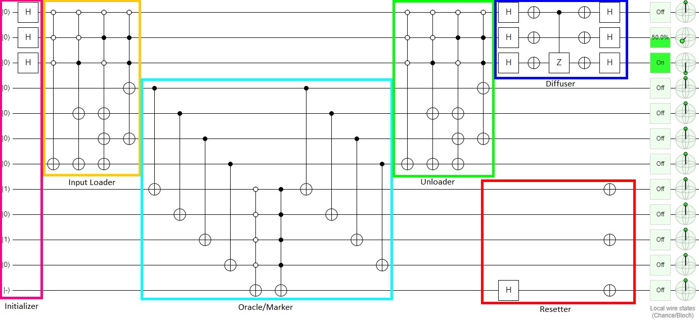
Input loading consists of exactly
-
The multi-control part acts on
n address qubitsand the multi-NOTs part onm data qubits. -
The application of the multi-controls is defined as follows:
- The control points of the ith gate from left corresponds to the ith index.
- The control points on the jth qubit from the top (in the diagram) corresponds to the jth bit in the binary representation of the ith index.
- A '
' or
anti-controlcorresponds to a0and a '' or
controlcorresponds to a1. - For e.g.:
- If the index is 5 in a 4-qubit control structure, the control points will look like '
' corresponding to
0101. - Similary, if the index is 11, in an 4-qubit control structure, the control points will look like '
' corresponding to
1011.
- If the index is 5 in a 4-qubit control structure, the control points will look like '
-
The application of the multi-NOTs or multi-Xs are defined as follows:
- The X in ith gate corresponds to the data of ith index.
- The X in jth data qubit corresponds to the jth bit in the binary representation of data in ith index.
- A '
' (or no X gate) corresponds to a
0in the data, and a '' corresponds to a
1 - For e.g.:
- If the data to be stored is 18 in a 5-qubit data, the gates will look like '
' corresponding to
10010. - Similarly, if the data to be stored is 3 in a 5-qubit data, the gates will look like '
' corresponding to
00011.
- If the data to be stored is 18 in a 5-qubit data, the gates will look like '
- We need the Oracle to mark the states which satisfy the condition
- First of all, we check if the values of the data qubits are either:
- exaclty the same as the number we are searching for, or
- the exact bitwise complement of the number we are searching for.
- We then mark those states which satisfy one of the above conditions, by
bringing a -ve phaseinto the qubits - The function of the oracle can also be interpreted as reflection about the marked states
- The CNOT gates compare the individual
(search state) qubits and the individual
(data) qubits.
- The gate will return a
if the two states are same and a
if they are complementary to each other.
- The
multi-anti-control-Xgate will act on the ancilla only if all the - Similarly, the
multi-control-Xgate will act on the ancilla only if all the - When one of the gates acts on the ancilla, there is a bit-flip.
(It easy to see that at most one of the gate can act as the
Sochanges to
which is same as
- The diffuser gate is applied to amplify the amplitude of only the required states of the indices.
- Mathematically, this step is described by the unitary operator
- It is effectively a reflection of the current state
of indices about the state of uniform superposition
of all the indices.
- I have reset the qubits other than the address qubits to the
retrieve the address qubits exclusively - Please note here that this reset operation is actually a series of
unitary operations(and hence reversible) unlike the non-unitary reset operation for QuantumCircuits provided by Qiskit
- Since we had taken an additional qubit to make sure that Grover's algorithm doesn't encounter more marked states than unmarked states, we are getting an additional qubit
- I have expressed the final state in the form of a statevector so that all information (amplitude along with phase) about the final state can be checked. The final statevector |psi⟩_idx gives the amplitudes of the basis states (as is expected).
For e.g.: - The statevector of the whole circuit has dimensions
. But, I have obtained the final statevector of dimensions
The oracle and the diffuser part need to be applied for approximately iterations. (n and k defined above)
I have tested this algorithm for random cases including those where the numbers satisfying the conditions are repeated, and it seems to work fine, apart from very small errors in some cases. It works best with inputs where the ratio of number of marked states to the number of unmarked states is very low. It should give the final states which are close to the correct state, almost always, for any general input.
- Since Qiskit is little endian, if we want to initailize first three qubits of a circuit to '10', the initialization unitary will initialize qubit_0 to 0, qubit_1 to 0.
- Similary if we want to see the Operator matrix of a gate or the statevector version of the result. The qubit order we see in Qiskit diagrams corresponds to the vectors and matrices in the opposite order of qubits
- I wanted to show all the results as we perceive (i.e. Big Endian convention). So, wherever I have used the statevector representation I have used the
Statevector.reverse_qargs()method.
I think for the overall complexity of the search algorithm, we should only consider the Oracle and the Diffuser and not the Input Loading part.
- [1] Michael A. Nielsen, Isaac L. Chuang - Quantum Computation and Quantum Information
- [2] Olivia Di Matteo - A primer on quantum RAM - [https://github.com/qsharp-community/qram/blob/master/docs/primer.pdf]
- [3] John A. Cortese, Timothy M. Braje - Loading Classical Data into a Quantum Computer - [https://arxiv.org/pdf/1803.01958.pdf]
- [4] Vittorio Giovannetti, Seth Lloyd, Lorenzo Maccone - Quantum random access memory - [https://arxiv.org/pdf/0708.1879.pdf]
- [5] Pang Chao-Yang - Loading N-Dimensional Vector into Quantum Registers from Classical Memory with O(logN) Steps - [https://arxiv.org/pdf/quant-ph/0612061.pdf]
I could complete this task by working collaboratively with my friend, Arya Bhatta who is also applying as one of my teammates for the QOSF Mentorship program. We did a lot of research together for the overall idea for the implementation as well as for small optimizations in circuit design, and after a lot of hours of discussing and arguing we finally managed to implement this beautiful working algorithm.