Status: Completed Type: ELE504 Lab
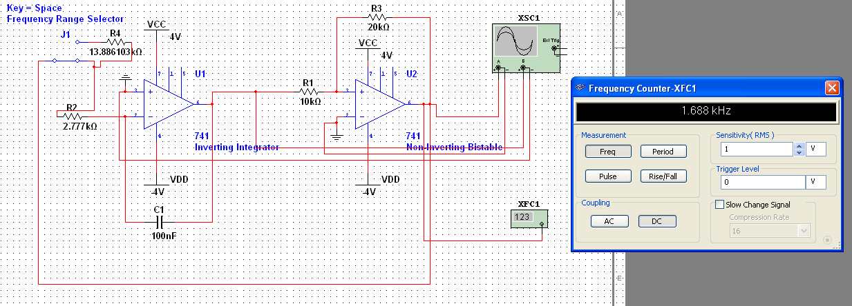
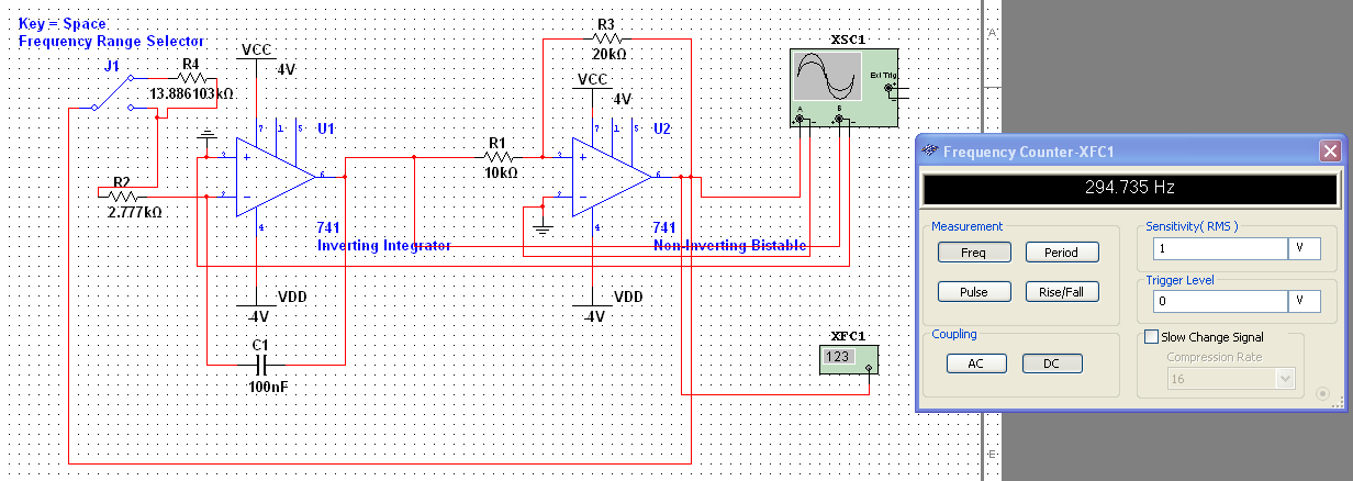
The purpose of this lab is to design and develop a linear voltage-controlled function generator (VCFG), and design it in such a way that it meets the user specifications. The user’s specifications is as followed:
-Triangular or Square wave output (User Selectable)
-Range #1 ≈ 100 Hz to 1800 Hz -Range #2 ≈ 20 Hz to 360 Hz Both ranges user selectable
-0.1V to 5V
-0V to 8V pk-pk
This project was a steady process to design a waveform generator. I first started with the basics/fundamentals of the design. The main hurdle is the actually generating two types of frequencies in the same Op-Amp circuit.
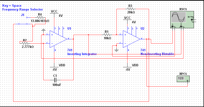
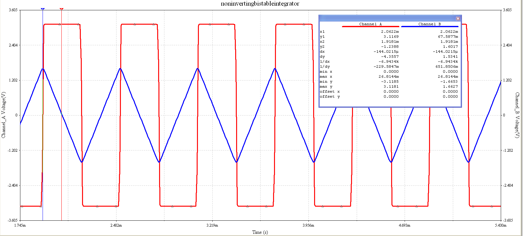
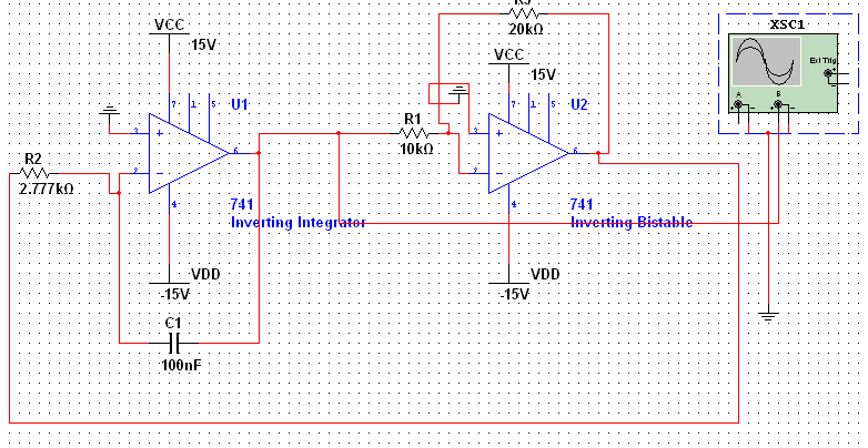
As can be seen in this repository. The wave generator was a compilation of many different types of circuits put together.
NOTE: The calculations are done assuming that the op-amp is ideal.
To be Updated
To achieve the user specifications of having the ability to generate triangle waves, an inverting integrator must be used.
As the integrator circuit takes in the square input from the comparator circuit, it integrates the square wave, thus outputting a triangle wave. The integrating property of the inverting integrator comes from the capacitor in the circuit.
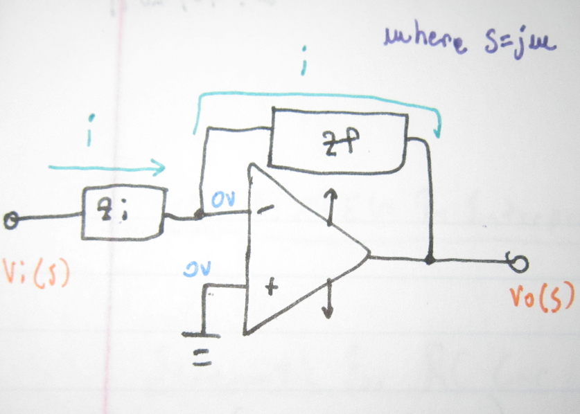
Basic layout of inverting integrator
As shown above, the schematic of the inverting integrator now includes a capacitor.
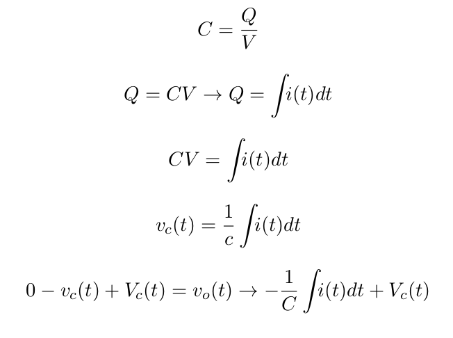
Before we get the formula however we must acquire the basic mathematical expression for the capacitor in time domain. The reason we use time domain in this case is because the integration of the output voltage will be easily seen.
In time domain, we must not only take into account the capacitance of the capacitor but also it’s initial voltage as well.
Subbing in the vc(t) equation into the vo(t) equation.
C => capacitance (farads)
Q => charge held on the plates in coulombs
V => voltage (V)
vc(t) => varying voltage over time in capacitor
Vc(t) => initial voltage in capacitor
KCL is then done on the circuit and the final equation seen at the bottom of the figure is the result.
Vo and vo are the output voltage of the circuit.
Thus the resulting equation is:
From the equation it can seen that the inverting portion is from “-” sign in front of the 1/RC.
The vi(t) is then integrated and added to Vc(t), initial voltage of capacitor.
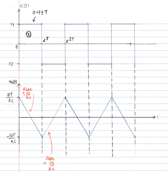
This can be seen in the figure below:
As can be seen from the figure above the integral of a positive square pulse is an inverse linear line and vice versa for a negative square pulse.
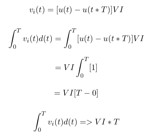
This is can mathematically shown to be true by the following calculations.
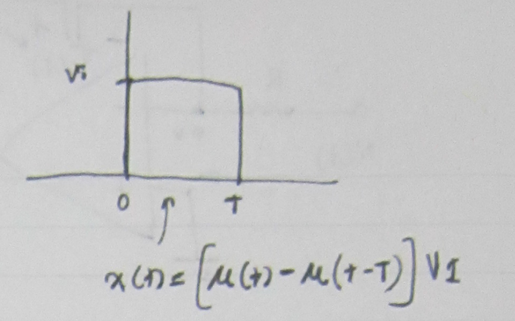
First by taking the positive portion of the square wave as shown in the figure below:
The following calculations can be done for it:
The last equation can be subbed into the previously derived equation in terms of Vo.
After which, the following calculations can be done.
Which matches up with example waveform diagram.
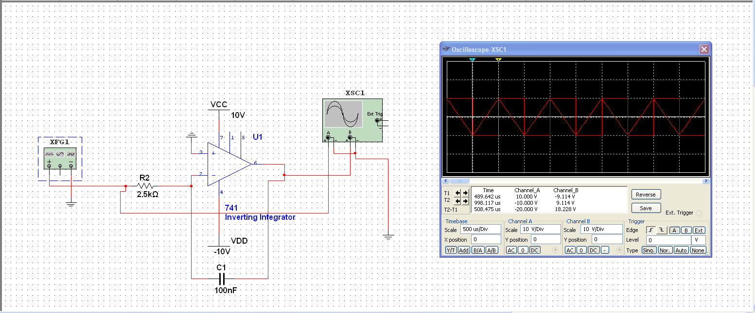
As can be seen from this Multisim simulation, a 5 Vpk-pk square wave (Channel A) is being inputted into an inverting integrator which is then inverting and integrating the input and outputting it to Channel B.
If the resistor values and capacitor values can be found for a desired slope and vice and versa.
Now that the triangle wave generator is figured out, the next step would be to develop the square waveform generator using a bistable multivibrator.
Now that the we have figured out the triangle wave generator, it is time to figure out the square wave generator.
The square wave generator will act as both an input for the triangle wave generator and one of the outputs waveforms that the user can select.
This will be done through a bistable multivibrator or also known as a comparator with hysteresis.
A basic comparator will saturate to its L+ and L- supply voltages if the input voltage on the positive terminal is larger than the voltage on the negative terminal.
Problems can occur if the voltage on the negative terminal is grounded. This means that any voltage on the positive voltage will cause the op-amp to saturate to L+, this also includes minute voltage levels from noise.
Therefore, the voltage on the negative terminal must be at an appropriate voltage level, so the intended voltage levels inputted into the positive terminal will trigger the op-amp to saturate.
This process is known as hysteresis.
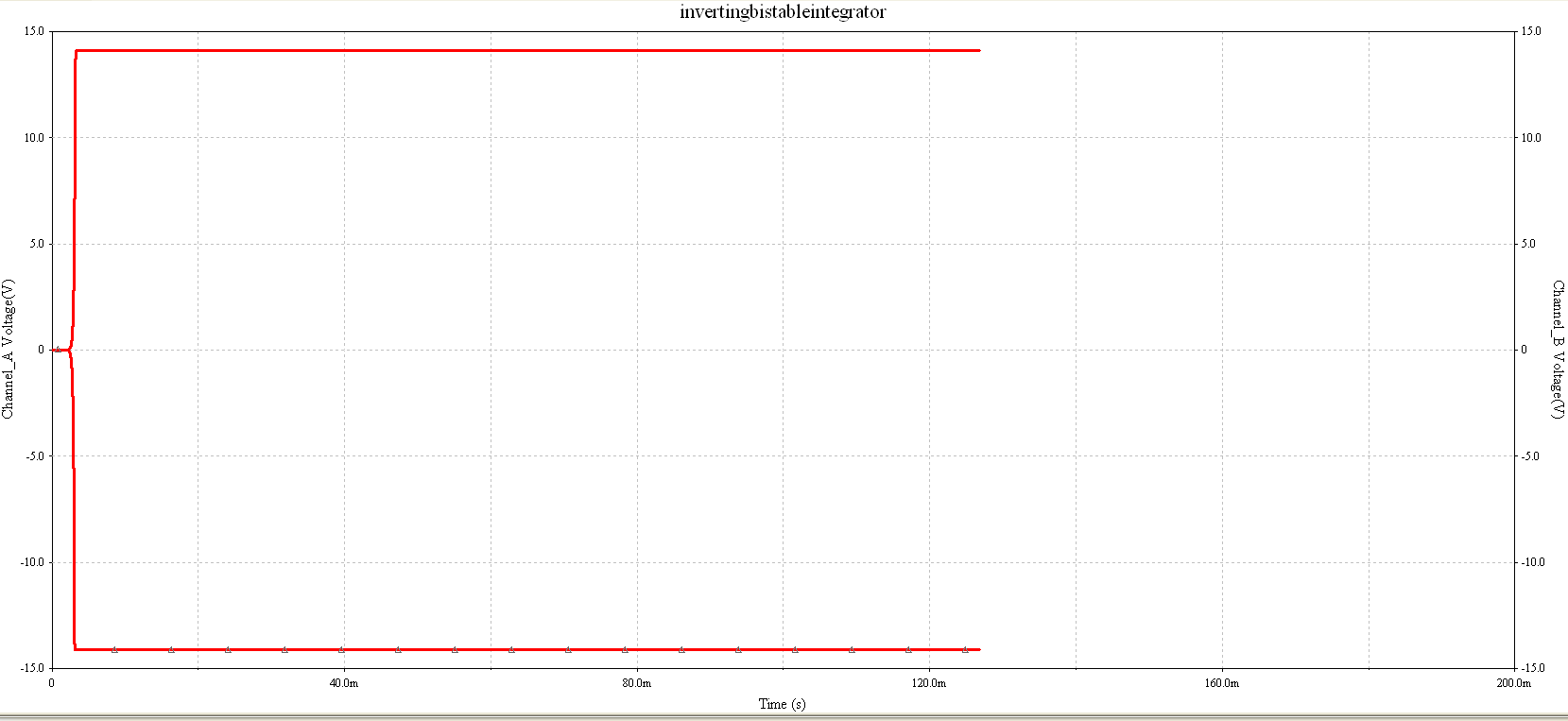
For this linear waveform generator, we will be using the non-inverting bistable since the inverting bistable will not work for this application.
to be updated
To be Updated
