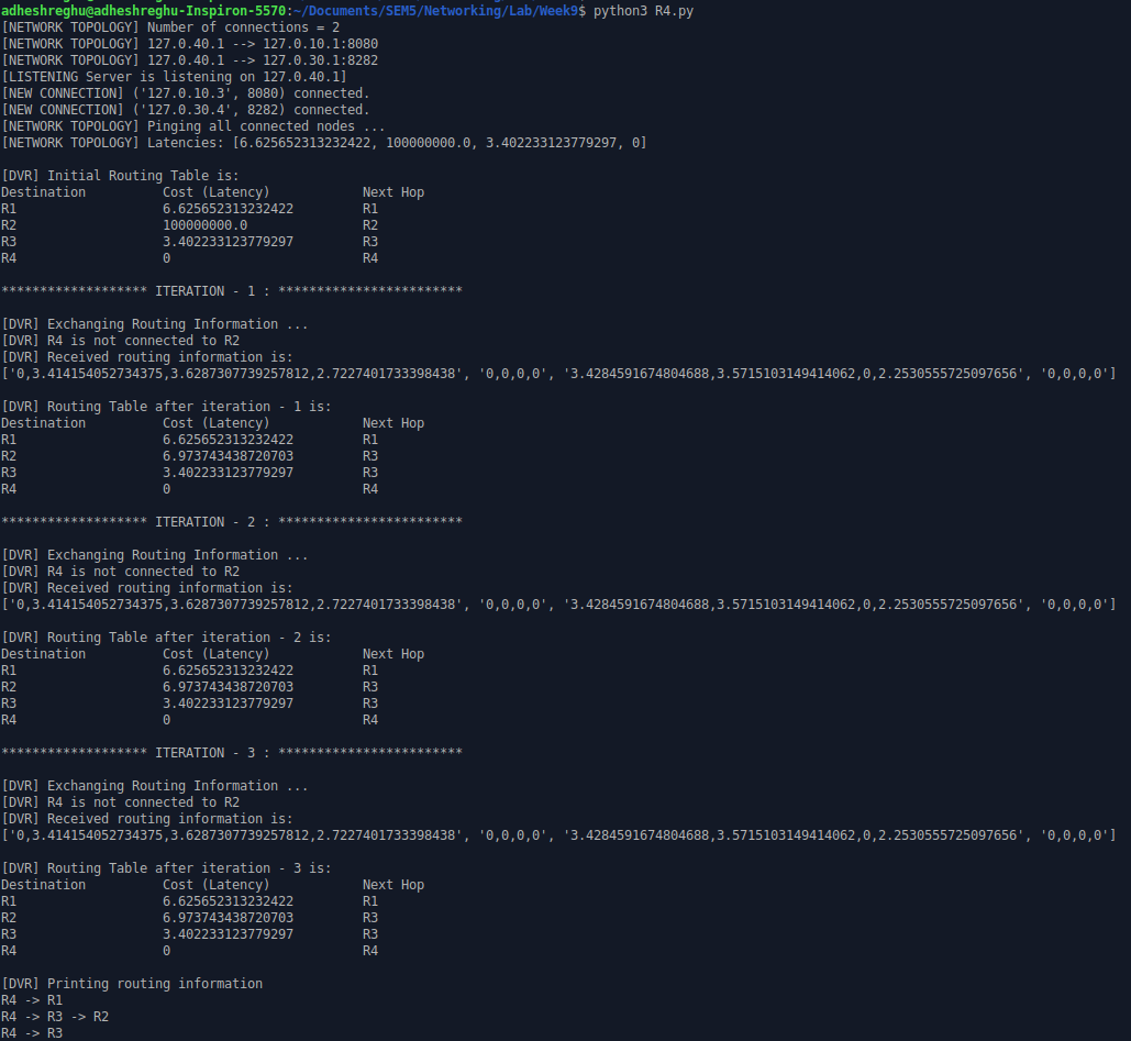
In this program we are supposed to simulate the Distance Vector Routing (DVR) algorithm using socket programming.
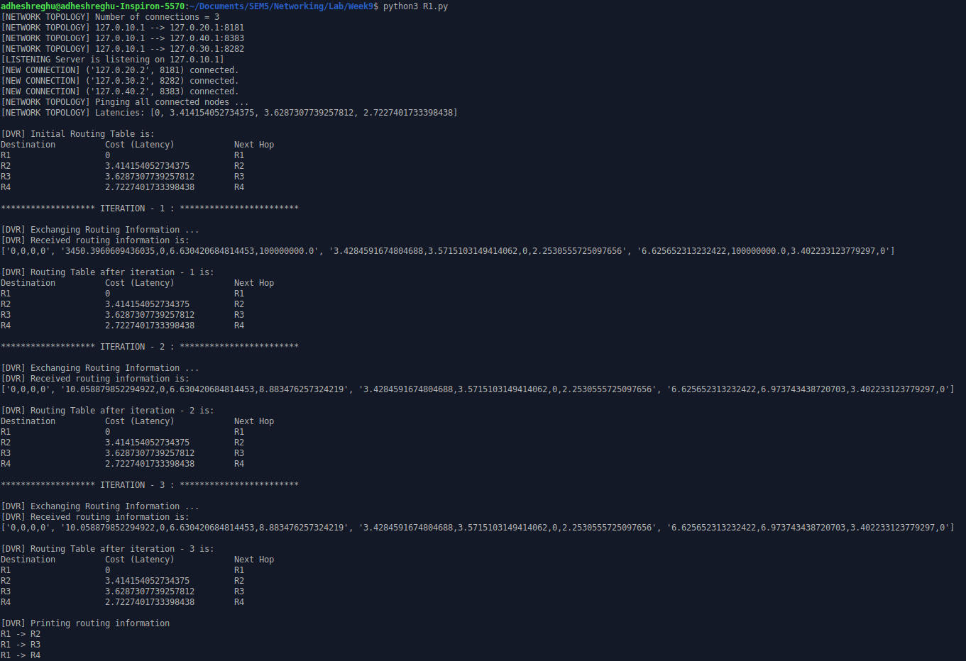
python3 R1.py
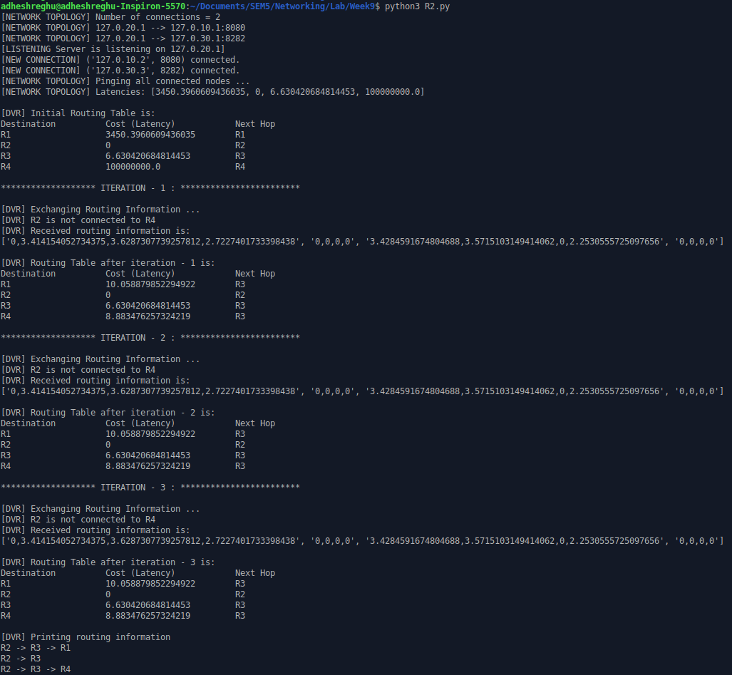
python3 R2.py
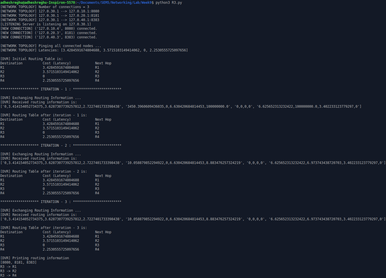
python3 R3.py
python3 R4.py
For this, we have to set up four nodes in a network and check the link cost based on the latency (RTT) of sending a message to one another . Using the latency as the cost, we will implement the DVR algorithm. The entire program can divided into the following steps:
Step 1: Setup the four nodes in the network -
To do this, we need information about the topology of the network, i.e, the connection details of each node such as the neighbors, ip address of the node and the port it is hosted on.
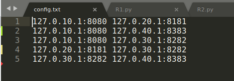
For this exercise, since the four nodes are hosted within the same network, each can be uniquely identified by their corresponding PORT NUMBERS. The topology information is stored in a config.txt file. Let us look at a sample config file.
The network topology corresponding to the given configuration file is:
Step 2: Setup servers and clients to emulate the node connections.
Each node will be a TCP server to which the neighboring nodes (as TCP clients) will connect to using separate client sockets. Each node should also be clients (TCP clients) so that the neighboring nodes can also know of the connections. This can be achieved using just server-server connection but since a TCP model doesn’t permit such
connections, we use client connections instead.
Step 3: From each node let us ping (send and recv message) to each of its connections and find the latency in terms of RTT.
Once we have all the nodes setup, we can send a standard message and time the response duration to compute the latency in terms of RTT. We also have to set up threads to manage incoming pings for each node so that there is no blocking in response.
Step 4: Initialise the DVR table
Based on the RTT obtained in step 3, we create the initial DVR table. It contains the three columns:
- Destination
- Cost (latency)
- Next hop
Step 5: Update the DVR Table
This is the main part of the entire program. In this step, each node shares its latency information with each of its connections. Once the routing information is shared, DVR algorithm determines the minimum path to reach the destination node from a given source node via the shared node. It employs Bellman's shortest path algorithm for this purpose.
Based on the algorithm, the update happens to the current routing table and the next hop and cost might change. The algorithm has to run for 3 iterations (in a 4 node setup) to find the shortest path from source to destination. Within the 3 iterations, each node would have explored all possible paths and found the shortest path from current node to every other node.
Step 6: Find the routing path from each node to every other node
Once the DVR table is updated, we would like to print the path that node takes to every other node. To do this we would also need next_hop details from other nodes as well. So in each node we set up a thread to respond with information in the node’s routing table if requested. In this manner, if a node wants to know the next_hop after an intermediate node, it can request that information from the intermediate node. In this manner the routing information is printed.
