![]()


ESPHome example configuration to monitor and control a pipsolar inverter via RS232
Kudos to @andreashergert1984 for the great work!
- PIP4048 compatible PV Inverter
- ESPHome 2022.11.0 or higher.
- One half of an ethernet cable with RJ45 connector
- RS232-to-TTL module (
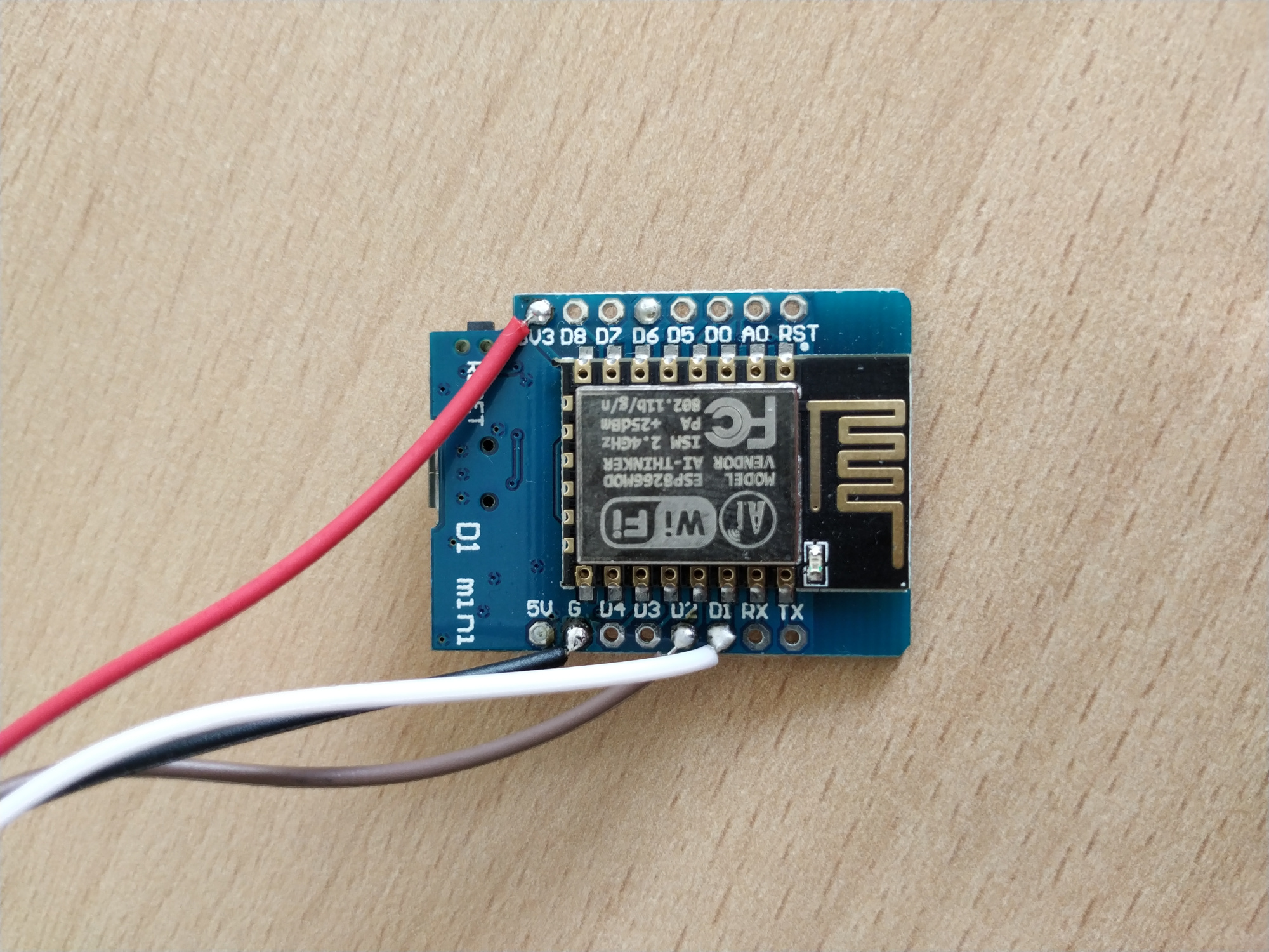
MAX3232CSEf.e.) - Generic ESP32 or ESP8266 board
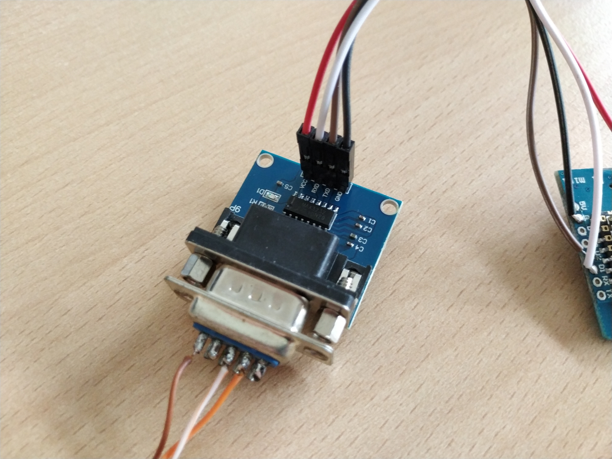
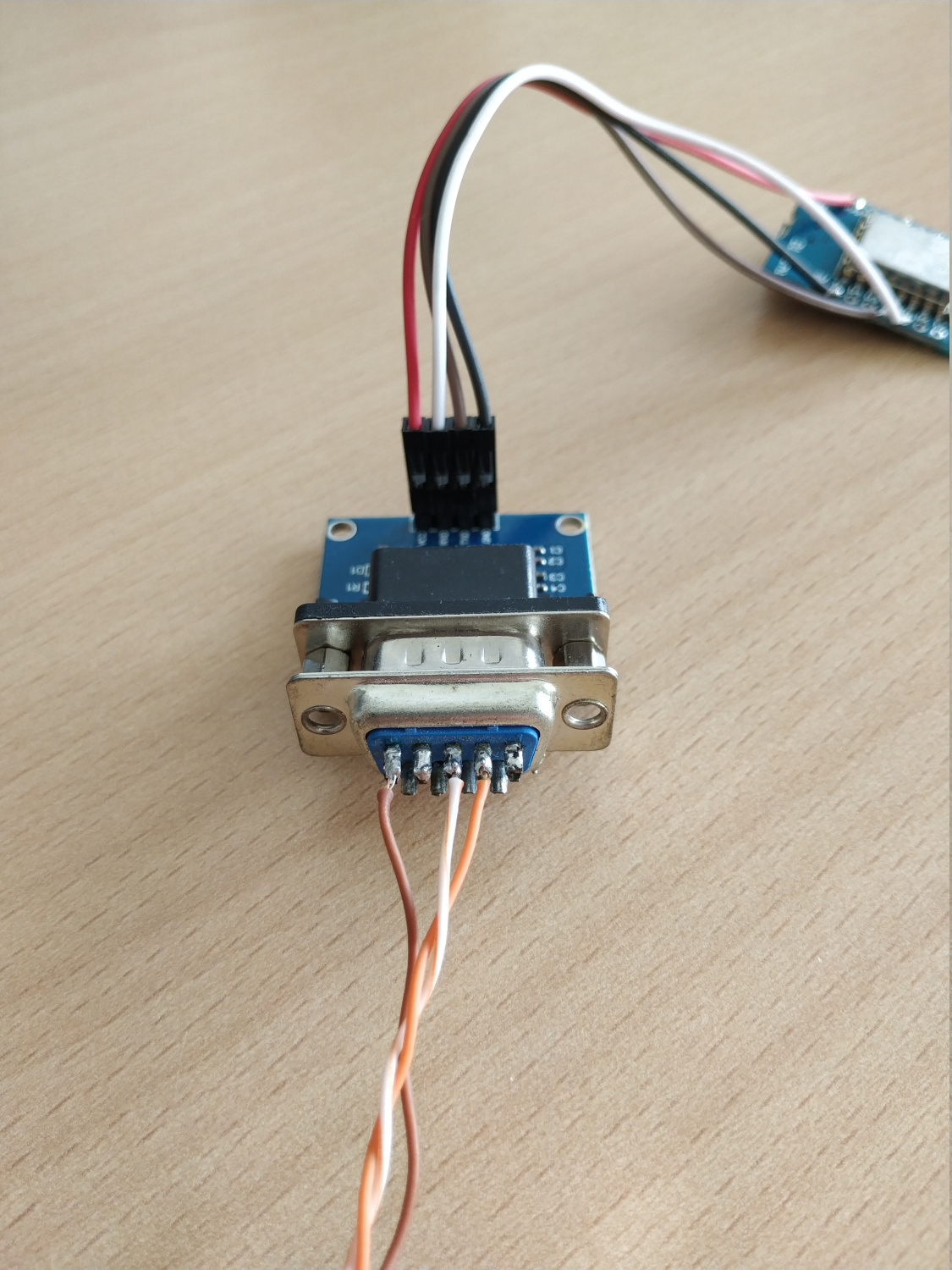
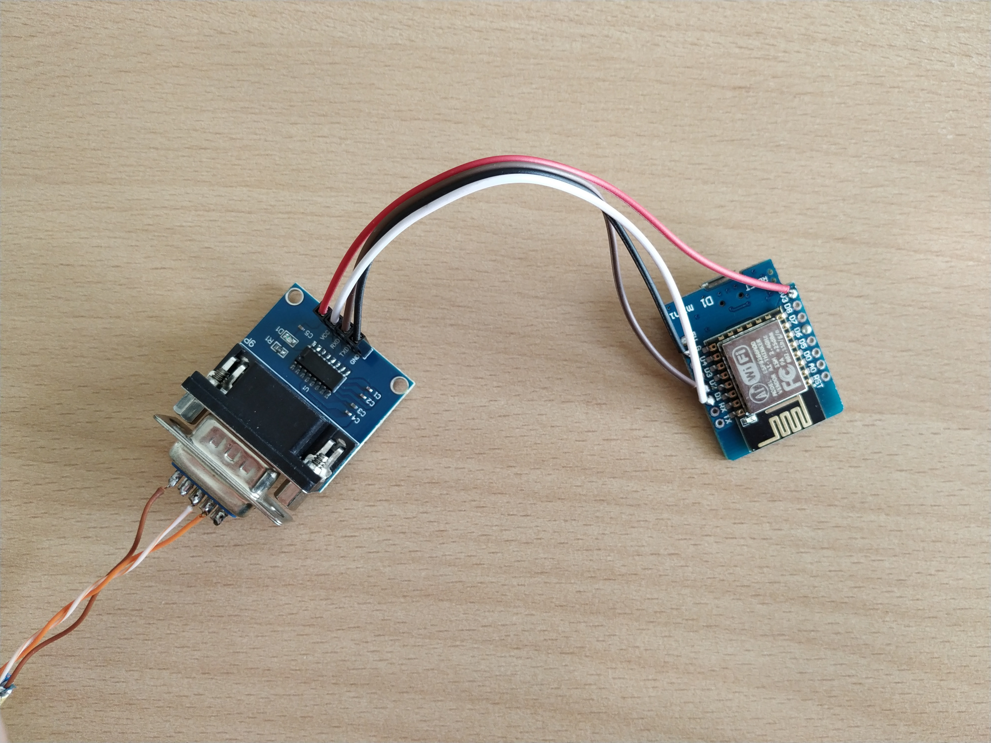
               RS232                     UART-TTL
┌──────────┐              ┌──────────┐                ┌─────────┐
│          │              │          │<----- RX ----->│         │
│          │<---- TX ---->│  RS232   │<----- TX ----->│ ESP32/  │
│   PIP    │<---- RX ---->│  to TTL  │<----- GND ---->│ ESP8266 │
│          │<---- GND --->│  module  │<-- 3.3V VCC -->│         │<--- VCC
│          │              │          │                │         │<--- GND
└──────────┘              └──────────┘                └─────────┘
| Pin | Purpose | MAX3232 pin | Color T-568B |
|---|---|---|---|
| 1 | TX | P13 (RIN1) | White-Orange |
| 2 | RX | P14 (DOUT1) | Orange |
| 3 | |||
| 4 | VCC 12V | - | Blue |
| 5 | |||
| 6 | |||
| 7 | |||
| 8 | GND | P15 (GND) | Brown |
Please be aware of the different RJ45 pinout colors (T-568A vs. T-568B).
The inverter provides +12V on pin 4 or 7 depending on the model. You can use a cheap DC-DC converter to power the ESP with 3.3V.
The source for the pinout is here.
| Pin | Label | ESPHome | ESP8266 example | ESP32 example |
|---|---|---|---|---|
| P11 (DIN1) | TXD | tx_pin |
GPIO4 |
GPIO16 |
| P12 (ROUT1) | RXD | rx_pin |
GPIO5 |
GPIO17 |
| P16 (VCC) | VCC | |||
| P15 (GND) | GND |
Use the esp32-example.yaml / esp8266-example.yaml as proof of concept:
# Install esphome
pip3 install esphome

# Clone this external component
git clone https://github.com/syssi/esphome-pipsolar.git
cd esphome-pipsolar

# Create a secret.yaml containing some setup specific secrets
cat > secrets.yaml <<EOF
wifi_ssid: MY_WIFI_SSID
wifi_password: MY_WIFI_PASSWORD

mqtt_host: MY_MQTT_HOST
mqtt_username: MY_MQTT_USERNAME
mqtt_password: MY_MQTT_PASSWORD
EOF

# Validate the configuration, create a binary, upload it, and start logs
# If you use a esp8266 run the esp8266-examle.yaml
esphome run esp32-example.yaml
Take a look at the official documentation of the component for additional details.
- If you configure a lot of the possible sensors etc. it could be that you run out of memory (on esp32). If you configure nearly all sensors etc. you run in a stack-size issue. In this case you have to increase stack size: esphome/issues#855
If this component doesn't work out of the box for your device please update your configuration to enable the debug output of the UART component and increase the log level to the see outgoing and incoming serial traffic:
logger:
  level: DEBUG
  # Don't write log messages to UART0 (GPIO1/GPIO3) if the inverter is connected to GPIO1/GPIO3
  baud_rate: 0

uart:
  id: uart_0
  baud_rate: 2400
  tx_pin: GPIO1
  rx_pin: GPIO3
  debug:
    direction: BOTH
    dummy_receiver: false
    after:
      delimiter: "\r"
    sequence:
      - lambda: UARTDebug::log_string(direction, bytes);
If you don't know the protocol of your inverter please use this configuration and try to identify to which request (>>>) your inverter responds (<<<). NAK is a negative response f.e. if the command isn't supported. If you have trouble to interpret the log please create an issue and provide your ESPHome log.