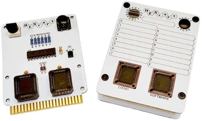
HEXcart is a cartridge for the Commodore 64. It can fit 16pcs of 8 or 16kB ROM images and supports regular and ultimax ROMs. The cartridge was designed mainly for diagnostics use with different tools like Dead Test and Diagnostics. Selection is done with a hex-switch so it can be used with a faulty C64 without any selection menus.
HEXcart contains two flash ROM ICs, U1 and U2. One is used for software and the second one is for logic. The softawe ROM IC must be at least 256kB in size to fit 16 pcs of 16kB ROM images.The logic ROM IC is used to set the EXROM and GAME signals to the correct state for regular or ultimax ROMs. No need for jumpers or switches. The EXROM and GAME signals need to be in the correct state so the cartridge ROM is mapped into the correct address space.
The hex-switch outputs go to a transparent latch IC U3. The latch is used for saving the state of the hex-switch during power-up/reset. This allows to set the hex-switch to different position while the machine is on. The new selected ROM is activated at the next power-up/reset. The LE (latch Enable) input of the latch IC is low active. Reset signal is therefore inverted with fet Q1 and resistor R2. If you don't need this latch feature you can leave out U3, Q1 and R2. Circuit is then replaced with four jumpers shorting pads 2&19, 3&18, 4&17 and 5&16 of U3 footprint. Short positions are marked on the PCB.
The hex-switch signals control the 4 highest address inputs of the software ROM IC. Therefore the hex-switch can select 16 different 16kB slots. The software ROM IC is enabled if either ROML or ROMH signal is low. This is done by diode-OR circuit with D2 and D3. The low active ROML and ROMH signals are used by the C64 to select low or high half of the 16kB ROM. That is why ROML signal must be connected to software ROM IC address pin A13.
The hex-switch signals control the 4 lowest address inputs of the logic ROM IC. Therefore it selects one of the first 16 bytes. These bytes are used to program the type of the cartridge. Outputs DQ0 and DQ1 control the GAME and EXROM signals. For example if the fift 16kB slot in the software ROM IC contains a regular 16kB game then the fift byte of the logic ROM IC must have two lowest bits zero.
Notice you can disable the cartridge by setting the hex-switch to an empty slot. If a slot is empty the flash content is FF by default. This sets the GAME and EXROM signals high and shows to the C64 as there is no cartridge. This does not work with C128 as it does not used the GAME and EXROM signals.
Use following or equivalent components for the PCB. U1 and U2 are not soldered but installed into sockets. U1 can be SST39SF020A or 040. U2 can be the same or also smaller SST39SF010A. There are also other voltage and pinout compatible ROM ICs.
| Definition | Manufacturer | Manufacturer PN | Designator | Quantity |
|---|---|---|---|---|
| CAP CER 100nF 50V X7R TH 200mil | KEMET | C330C104K5R5TA | C1, C2, C3 | 3 |
| DIODE SMALL SIGNAL 100V AXIAL | onsemi | 1N4148 | D2, D3 | 2 |
| MOSFET N-CH 60V 500MA TO92-3 | onsemi | BS170-D27Z | Q1 | 1 |
| RES 10K OHM 1% 0.6W AXIAL | Yageo | MF0207FRE52-10K | R1, R2, R3, R4, R5, R6 | 6 |
| SWITCH ROTARY DIP HEX 0.15A 42V | Same Sky | RDS3-16S-1065-1-D | SW1 | 1 |
| SWITCH TACTILE SPST-NO | Omron Electronics | B3F-4050 | SW2 | 1 |
| IC FLASH 2MBIT PARALLEL 32-PLCC | Microchip Technology | SST39SF020A-70-4C-NHE | U1, U2 | 2 |
| IC D-TYPE TRANSPARENT LATCH 8:8 20-DIP | Texas Instruments | SN74HC573AN | U3 | 1 |
| SOCKET PLCC-32 TH | Adam Tech | PLCC-32-AT | (U1, U2) | 2 |
Use the following or similar part for assembly. If you don't need the PCB case then leave out all except the cartridge PCB. Top and bottom cover PCBs can be flipped around to have different PCB artwork. One side of the top cover got a premade list for marking the ROM image names. The other side is almost blank for printed labels.
| Definition | Link | Quantity |
|---|---|---|
| Cartridge PCB | https://jlcpcb.com/ | 1 |
| Top cover PCB | https://jlcpcb.com/ | 1 |
| Bottom cover PCB | https://jlcpcb.com/ | 1 |
| M3x4 screw | https://www.aliexpress.com/item/1005003640441632.html | 12 |
| M3x6 standoff | https://www.aliexpress.com/item/32832544494.html | 8 |
| M3x8 set screw | https://www.aliexpress.com/item/1005005720795823.html | 2 |
| Reset switch hat | https://www.aliexpress.com/item/1005006228397255.html | 1 |
Gerbers can be downloaded from HERE.
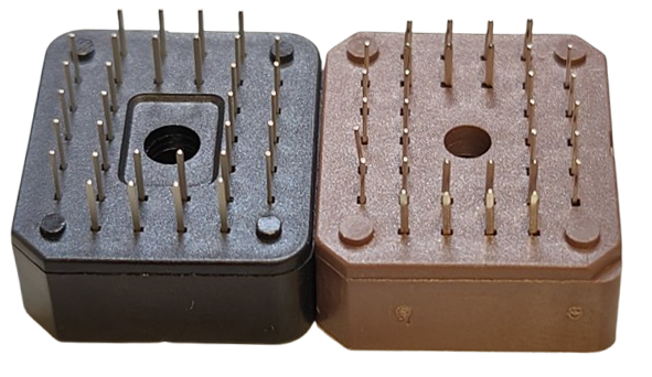
PLCC sockets have tabs on the bottom. Cut them away with side cutters or with a knife. This allows the socket to sit flush or slightly below the front cover.
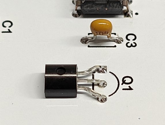
Bend the pins of fet Q1 so it sits horizontally against the PCB. In straight position the front cover wont fit. The cover PCBs are reversible. The top cover has a table on one side. Other side is mostly blank for printed labels. The bottom cover can have white or honeycomb pattern visible.Assemble the PCBs and standoffs. The standoffs at the right are connected together with the set screw.
The software ROM IC got 16 pieces of 16kB slots. If you have an 8kB ROM image then it's easiest to copy it twice to fill a 16kB slot. If you use empty space instead then a regular 8kB ROM must be in the lower half of the slot. An 8kB ultimax ROM image must be in the upper half.
Cartridge ROM images can be found as raw .bin or .hex files. These can be directly combined and programmed into the ROM IC. ROM images can also be found as .crt files. These files got extra information at the start of the files for emulators etc. You can use cartconv.exe to extract .bin file of the .crt file. Use command cartconv -i "input.crt" -o "output.bin" for extacting the .bin file. The output text also tells you what kind of cartridge it is.
The .bin or .hex can be directly imported to a programming software like Xgpro or combined beforehand. In Windows use copy /b file1.bin+file2.bin combined.bin. In Linux the command is cat file1.bin file2.bin > combined.bin.
Programming of the logic ROM IC is simple. Just open Xgrpo or other flashing tool software. Edit the first 16 bytes to match the ROM image types in the software ROM IC. Set the low nibble to 0, 1 or 2 as in following table. High nibble does not matter and can be left as default "F" or set to 0.
In the image below the logic ROM is programmed to set EXROM and GAME signals for a 16kB ROM in slot 0, 8kB ROM in slot 1 and a ultimax ROM in slot 3. The rest of the slots 3-F are empty.See HERE.
HEXcart by Pasi Lassila is licensed under CC BY-SA 4.0


