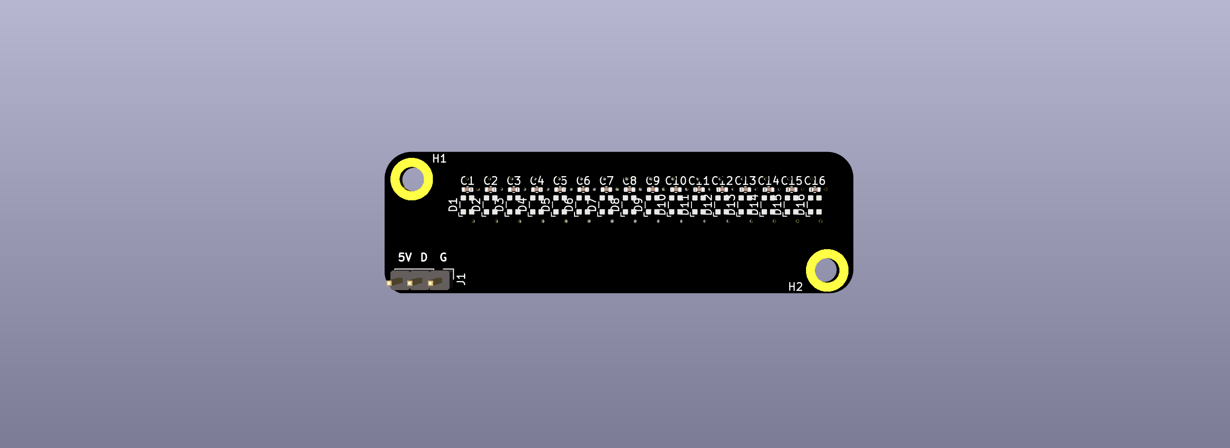
| front | back | lightbar |
|---|---|---|
 |
 |
 |
unfinished attempt to re-create pcb and lightbar for matrix 1.2og.
this has been designed by using pcb edge cuts and plate file that were provided courtesy of astro of matrixlab here. without it, re-creating the PCB would be a more maddening and expensive experience. it has 19.02mm x 19.02mm spacing (mostly).
indicator LEDs on scroll lock and caps lock. JST headers are for s3b ph 3 pin, since that's what it looks like from watching youtube build videos.
- The official plate file is treated as the source of truth for where switches should be placed
- The official 1.2OG PCB edge cuts provided by astro has some arcane spacing rules -
- 19.02mm on y axis for every row
- 19.02mm on x axis on first three rows and all arrow keys
- 19.00mm on row 4 on the main cluster of keys (not arrow keys)
- The right shift key might still be at where it would be at 19.02mm spacing. The left shift key, i'm not sure, I just placed it where it would have been at 19.02mm spacing.
- 18.978mmm on modifier keys in the bottom row (not sure if spacebar key is affected)
- all of this is ignored in favor of sticking with plate dimensions or expected plate dimensions, which are 19.02mm x 19.02mm spacing, EXCEPT
- 19.024mm y-axis spacing between the function row and regular key cluster
- the distance between the
MandCommakey is 19.03mm.
- The official 1.2OG PCB edge cuts provided by astro has some arcane spacing rules -
- lightbar mounting holes on PCB are slightly off-spec, and in here are plated m3 (edge cuts seem to imply the hole is a bit wider).
- lightbar can now connected to PCB through a molex pico ezmate cable. if you don't like it, you can assemble without it, and solder the s3b connector on yourself.
- https://www.mouser.com/ProductDetail/Molex/36920-0301 - pick these up, and cut them down the middle to solder wires direct to lightbar
- split backspace and split right shift are included, in case anyone is wants to make a plate that supports those switches. ISO left shift and enter are not included due to laziness.
- usb port placement is mostly guessing.
- 6U spacebar support is added because I miss using my hhkb pro 2.
stm32f072 schematic is courtesy of xphoenixd. thanks for teaching me how to design PCB's, man. schematic for ws2812c-2020 rgb chain is inspired by zykrah's fuyu. voltage step-up thing for lightbar is inspired by schematic from fuyu and dededecline and olivia's sst60.
an earlier revision included a basic reset circuit provided by xyz, who also pointed out an issue in the BOM that caused one major issue with the first round of prototypes - were it not for him, I'd probably make two more rounds of protos with the same issue. all love to matthewdias, islandworks, and mel for pointing out a glaring issue with USB, and doubly so for matt for being willing to replace 0402 package resistors pro bono after xyz pointed out how a BOM mistake from me rendered the reset circuit useless. thanks to chippy, phoenix, and chill for misc. advice on how to design this.
i don't know if i'm allowed to license this, given the pcb edge cuts this is based off of were released without a license. nevertheless, they were provided by astro from matrixlab. thank you!
no working prototype has been made for this yet! beware!
fill out BOM real good- measure and source standoffs that are good enough and ultra low profile screws
split main pcb and lightbar pcb separately so jlcpcb production files don't keep bothering each other- adjust placement of ws2812 based on if it is too far to one side of the lightbar or the other.
- consider alternative to ws2812 2020 if power consumption/cost reasons.
- prototype PCB and lightbar
firmware (come on, this is basically automated at this point)- modify lightbar to support both direct soldering and ezmate/jst ach through mouse bite/break off thing or something
- i think there should be straight ezmate to this, it would make peoples lives so much easier (ignoring how you'd route the extra cable slack)
- verify this works with original lightbar
first revision (in beta branch) failed due to rookie mistake of using USB symbol from one library and footprint from another - the pins between each were in reverse order of each other, which made the prototype useless. whoops! after shipping PCBs to matt for rework, some goons looked over this in kicad pcbeditor and pointed out that the pins over USB were in reverse order.
second prototype arrived 5.31.2023, and exhibited strange behavior - on boot to bootloader mode, dfu-util is able to flash the PCB seemingly fine, and then after reset, the PCB appears recognized by VIAL, at which point every single device connected over the same USB hub goes unresponsive. the pcb is also unresponsive. five seconds pass, the PCB dissapears from VIAL, and USB devices begin working again. something deeply bad has happened, so I've tried rearranging all the parts, validating BOM, and praying next revision works.
the latest push to main branch uses molex 0548190519, which I haven't prototyped, but shouldn't be too different otherwise.
i've bought these SMT M2 threaded spacer/standoffs so that lightbar can mount to pcb - https://www.mouser.com/ProductDetail/Wurth-Elektronik/9774015243R - you're probably supposed to use solder paste to assemble these things, but I don't have that, so I don't know, maybe I'll use solder shavings to get these things soldered on. they're slightly smaller than the m3 plated hole on pcb/lightbar, but I don't think it'll matter too much, since they should align one way or another.