Phobia Motor Controller
PMC is an open project that aims to build the quality permanent magnet synchronous motor (PMSM) controller for use in a variety of scopes like RC or electrotransport.
ATTENTION: the repository is moving to sf.net.
Hardware specification (rev4c)
-
Dimension: 90mm x 50mm x 15mm.
-
Weight: 40g (PCBs) or 230g (with 20cm wires and heatsink).
-
Wires: 10 AWG.
-
Connector: XT90-S and bullet 5.5mm.
-
Supply voltage from 5v to 50v.
-
Phase current up to 120A (IPT007N06N, 60v, 0.75 mOhm).
-
Light capacitor bank (3 x 2.2uF + 3 x 680uF).
-
PWM frequency from 20 to 80 kHz.
-
STM32F405RG microcontroller (Cortex-M4F at 168 MHz).
-
Onboard sensors:
- Two current shunts (0.5 mOhm) with amplifiers (AD8418) give a measuring range of 150A.
- Supply voltage from 0 to 60v.
- Three terminal voltages from 0 to 60v.
- Temperature of PCB with NTC resistor.
-
Motor interfaces:
- Hall Sensors or Quadrature Encoder (5v pull-up).
- External NTC resistor (e.g. motor temperature sensing).
-
Control interfaces:
- CAN transceiver with optional termination resistor on PCB (5v).
- USART to bootload and configure (3.3v).
- Pulse input control: RC servo pulse width, STEP/DIR, QEP (5v-tolerant).
- Two analog input channels (from 0 to 6v).
-
Auxiliary interfaces:
- Two combined ports with: SPI, I2C, USART, ADC, DAC, GPIO (3.3v).
- BOOT and RESET pins to use embedded bootloader.
- SWD to hardware debug.
- External FAN control (5v).
-
Power conversion:
- Supply voltage to 5v buck (up to 1A).
- 5v to 12v boost (up to 100 mA).
- 5v to 3.3v linear (up to 400 mA).
- 5v to 3.3vREF optional reference voltage (accuracy 0.2%, 25 mA).
Look into phobia-pcb repository for PCB design source files.
Software features
-
Sensorless vector control of PMSM based on two inline current measurements.
-
Advanced PWM scheme to reduce switching losses and fully utilise DC link voltage.
-
Fast and robust multi-hypothesis flux observer (MHFO) with gain scheduling.
-
Terminal voltage sensing to reduce the effect of Dead-Time.
-
Automated motor parameters identification with no additional tools.
-
Self test of hardware integrity to diagnose troubles.
-
Flux weakening control (EXPERIMENTAL).
-
Terminal voltage tracking to get smooth start when motor is already running (EXPERIMENTAL).
-
Two phase machine support (e.g. bipolar stepper) (EXPERIMENTAL).
-
Advanced command line interface (CLI) with autocompletion and history.
-
Non critical tasks are managed by FreeRTOS.
-
Flash storage for all of configurable parameters.
-
Operation at low or zero speed:
- Forced control that applies a current vector without feedback to force rotor turn.
- High frequency injection (HFI) based on magnetic saliency (EXPERIMENTAL).
- Hall Sensors or Quadrature Encoder (TODO).
-
Control loops:
- Current control is always enabled.
- Speed control loop.
- Servo operation (EXPERIMENTAL).
- Battery charger (TODO).
- Voltage rectifier (TODO).
-
Adjustable limits:
- Phase current (with adjustable derate from overheat).
- Source current (or power) consumption and regeneration.
- DC link overvoltage and undervoltage.
- Maximal speed and acceleration (as part of speed control loop).
-
Control inputs:
- CAN bus (TODO).
- RC servo pulse width.
- STEP/DIR (TODO).
- Analog input with brake signal.
- Manual control through CLI.
- Custom embedded application can implement any control strategy.
-
Available information:
- Total distance traveled.
- Source energy (Wh) and charge (Ah) consumed (or reverted).
- Fuel gauge percentage.
- Peak values.
TODO
-
Analyse HFI operation on large current values.
-
Make a detailed documentation.
-
FIX: add detached motor Kv probing
Current Status
Now we can declare that PMC is ready to use in most applications. But there is still a lot of unresolved issues. It may be difficult to configure the PMC for a specific motor.
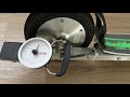
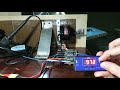
There are a few videos that show the operation of the prototypes (may be outdated).


Read more in Getting Started.