A real MOS 6502 connected to Virtual Memory/Devices
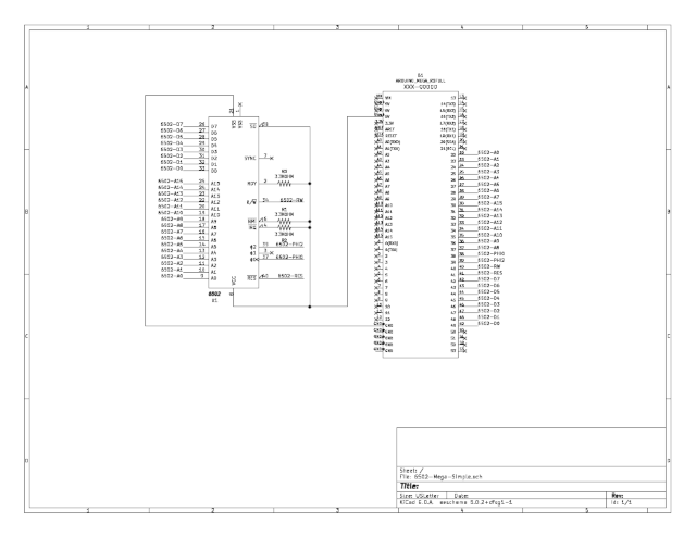
- ./ArduinoIDE/6502-Mega-Simple/
6502 Address Bus, Data Bus and Control Lines connected to an Arduino Mega 2560:
- Address Bus on ports PA and PC (22 to 29 and 37 to 30)
- Data Bus on port PL (49 to 42)
- Clock (PHI0) on PD7 (pin 38) - 5Hz to ¿100KHz?
- PHI2 on PG2 (pin 39)
- RW on PG1 (pin 40)
- RST on PG0 (pin 41)
- On every PH2 falling edge the data bus is put in High Impedance
- On every PH2 rising edge:
- pin 53 is high so you can see it on an oscilloscope
- the rw line and the data and addres bus is processed using C arrays as virtual RAM/ROM and that info is displayed on Serial
- pin 53 is low and you can see it on an osciloscoppe


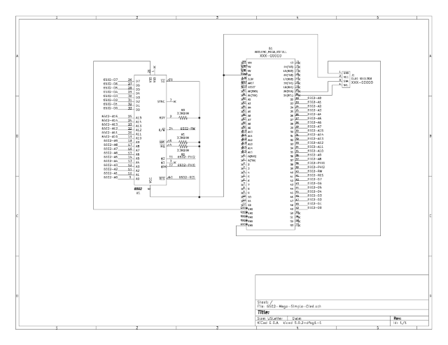
- ./ArduinoIDE/6502-Mega-Simple-Oled/
Same as (1), but add an oled SSD1306 is used instead Serial. Displaying data in the oled is slow

- ./ArduinoIDE/6502-Mega-Serial
Arduino Mega 2560 acts as a bridge between the 6502 CPU and a Python program as "memory" provider:
- Connect the board, select the FREQ_6502, adjust the Serial baud rate and upload the code
- Run "6502-Mega-FunctionalTest.py" (it uses a RAM/ROM image to test the 6502 - https://github.com/Klaus2m5/6502_65C02_functional_tests)
- Wait 3, 4 or 90 hours to finish (remember the 6502 clock)
