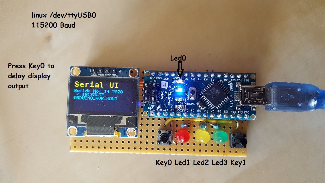
Arduino UI with OLED display, 4 led and two keys
Arduino Nano V3.0 with FTDI UART works :-) for B&R PLC
FTDI is working fine for B&R USB connection
CP210x is NOT working for B&R PLC (tested with ESP Board and serial small USB Serial 5V adapter)
CH340 is NOT working for B&R PLC (tested with ESPDuino)
EPS8266 CP2102 --> Does not work for B&R PLC's
Search for if you try to rebuild: Nano V3.0 FT232 Chip ATmega328 Atmega328p 16M
Check there is not a CH340 build in.
For Linux or Windows all variants are working without any problems.
- 115200 Baud, SERIAL_8N1 (the default)
4 led with commands. A sequence with multiple command is allowed. e.g 2p3f will show a pulse on led 2 and lets flash le3 3 10 times.
0,1,2,3 = select led, command is modal
x = off
o = on
p = 100ms puls
f = flash sequence 10 times fast
h = this help
To access the display to send texts to the display start with '@', this will forward all characters to the display.
With '#' and '|' you can change between small an big font.
'&' will clear the display.
To switch back to control the led use '^'.
^ = switch to led command
@ = switch to oled output
# = big font
| = small font
& = clear display
\ = new line
If the keys are pressed and released events are visible on the display and send to UART.
Following strings are send:
{"key0":true}
{"key0":false}
{"key1":true}
{"key1":false}
Led0 = BUILD IN LED
Led1 = D5
Led2 = D6
Led3 = D7
Key0 = 11; //D11;
Key1 = 12; //D12;
NodeMCU 1.0
Flash Size: 4M(3M SPIFFS)
I2C Bus:
SCK = D1 = GPIO 5
SDA = D2 = GPIO 4
Old Boot loader !!!
"board": "arduino:avr:nano"
"configuration": "cpu=atmega328old"
I2C Bus:
SDA = A4
SCL = A5
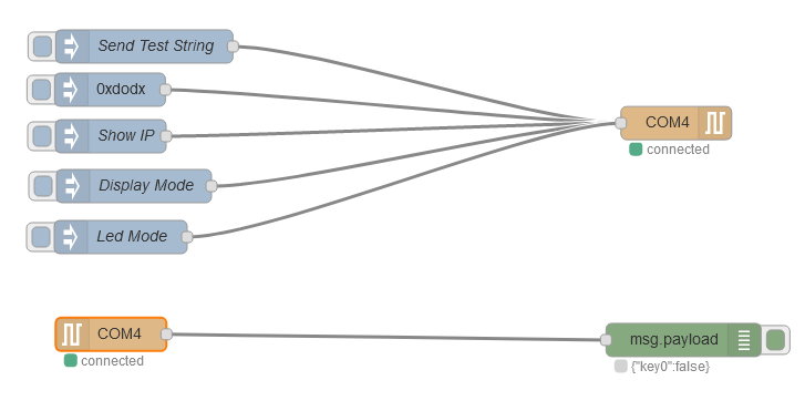
Simple to test the Arduino UI is to use Node-RED.
Import following JSON : test-flow-UART.json
If you clone this repo, to use node-red, you have to install node-red globally and then execute npm install in main folder and within node-red.
push --> commit to GIT
pull --> get from GIT
use commandos in VScode :-)
It seems the excessive debug logging is caused by running Java with -DDEBUG=true. Adding -DDEBUG=false to the C:\Program Files (x86)\Arduino\arduino_debug.l4j.ini fixes it for me.

