Since I left the university, I always wanted to gain a deeper understanding of how Kalman filters work in practice. I started to do research on the topic, until I found an excellent paper from Roger Labbe, describing the Bayesian filters in great detail and in a very practical way.
After reading the book, I wanted to implement it in a real-life project. Since I'm a passionate paraglider pilot, building a variometer was a straightforward direction for me.
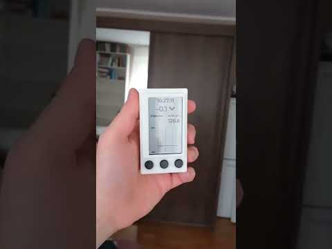
A variometer is a flight instrument, measuring vertical height and velocity, based on barometric pressure. Since pressure measurement is very noisy, in most cases (even in commercial products), a low pass filter is used to smoothen it, resulting in many seconds of lag in the output. This is how it has always been and this is something that every pilot has to learn how to compensate mentally, using prior experience and listening to other sources of information, like feeling of acceleration. It can be very hard to learn and master especially for beginners. To solve this, many people have already built variometers combining a pressure sensor and an accelerometer, with promising results.
I started to design the hardware, but I hit walls right at the beginning. The STM32 micros, that I have a lot of experience with, are not available due to global chip shortage, so I had to find an alternative. I choose ESP32, because it has lots of computing power, it is on stock and has additional built-in capabilities - like Bluetooth and WiFi - providing great potential for future developments.
The other crucial part of the project was to find the appropriate display. The special flying conditions require very good readability under any circumstances, therefore I choose the LS027B7DH01, a transflective LCD from Sharp, which I ordered from Digikey.
I used KiCad for PCB design and FreeCAD for the housing. You can find the project files in the hardware and housing folders.
While waiting for the PCB, I started to experiment with Arduino, but I had to realize quickly that it is not suitable for me. I changed to ESP IDF and it was a very good decision. I am satisfied with the framework, it has lots of documentation, clear examples, a well designed interface, and works out of the box.
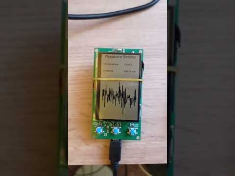
My first task was to fire up the sensors on the board, still using development kits:
- MS5611 pressure sensor: I know this sensor very well, it was an easy task to make it work. I connected it to the ESP32 using I2C
- LS027B7DH01: I used SPI to connect it to the MCU. I use the LVGL graphics library to implement the UI
- BNO055 IMU from Bosch, who provides the needed driver too
The MS5611 and the LCD were very easy, but I struggled with the IMU. Everything worked fine for some time, but after a few seconds or sometimes minutes, the communication stopped and only a power reset could solve the problem. A friend of mine lent me a Saleae Logic Pro 16, to investigate the issue, and I quickly found the root cause: the I2C clock stretching is not handled properly in the driver. After I added a timeout to mimic clock stretching, the issue disappeared and now the IMU works perfectly. The main issue was that BNO055 has a complex internal algorithm that takes some time to run, therefore it stretches the clock cycle until it finishes the task. The communication worked as long as the internal sensors were not ready, but after it had calibrated the system and started the algorithm, the communication stopped. I could have struggled a lot without a logic analyzer, because working with hardware without having a logic analyzer at hand is like solving a rubik's cube in a dark room without any visual feedback. Until each bit is in its exact position at the right time, the program does not work and it is very hard to find the root cause just by reading the code. I was amazed by the build quality of the Saleae device. It is very simple to use, although I found it annoying that the labels numbering the input channels are placed on the backplane of the housing. Other than that, it is clearly a professional tool made for heavy duty embedded development. The software is simple to install and straightforward to use even without reading the manual, because it is really intuitive. I also experimented with an SD card and Saleae logic analyzer to discover the potential of the device. It looks really cool!
SD card setup

Wiring

Decoded SPI frame

Decoded SPI byte

400kHz SPI clock signal

After making the board up and running, I sampled input data using real sensors, and started to experiment with Kalman filters. First, I designed an unscented kalman filter (UKF) using filterpy. I was truly satisfied by the results and started to work on my own implementation in C++.
Although the results were very promising at first sight, I encountered problems. I had to realize that the IMU has an orientation-dependent, constantly changing offset that introduces an unacceptable error in the final result. This offset is accumulated only in a standstill position and is eliminated internally when the device is moving, but it’s a bit annoying while waiting for take off.
The other, show stopper issue is that BNO055 is not suitable for this task. Since only the vertical acceleration is relevant for the computation, detecting the direction of the gravity vector is a crucial step. BNO055 fails to detect the vertical direction if the device is in a constantly accelerating situation and it provides false results. This happens when flying in a narrow thermal, resulting in a constantly beeping variometer indicating crazy climb rates, even though the vertical speed is minimal. This is totally unacceptable and I’m very disappointed. I didn’t recognize this problem early enough when selecting the accelerometer, although even the documentation does not emphasise it either. Only a small note states this behavior, which is very frustrating. Lessons learned ...
Considering the results, I decided to build a new device using 4 baro sensors and no IMU. This way I can increase the sampling rate and make the device more responsive to changes without the problems introduced by accelerometers. I could also try Madgwick's algorithm, but I decided to go in this direction first.
This project is still in concept phase, it requires a lot of work to finish it. Until then watch these videos and stay tuned!