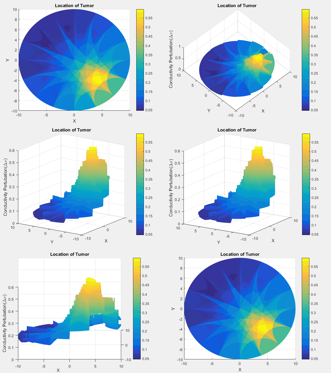
This project is to learn an application of applying Green's Functions towards Electrical Impedance Tomography (EIT) to image a simulated tumour in a circular region using MATLAB. This is part of a project course from the University of British Columbia.
See the resulting EIT scan as a gif!
Trouble viewing the GIF? Download the video here: Video.
Electrical impedance tomography (EIT) is an imaging method which uses surface measurements to determine variations in electrical conductivity, permittivity, and impedance within an object to image that specific object. It is highly used in medical imaging as it is noninvasive and biological tissues and fluids have considerable variations from each other in conductivity and is therefore distinguishiable using EIT.
In the regular set-up for an EIT system, surface electrodes are attached to the outer layer of the area being examined. Current is then applied to node pairs (located such that the examined area separates the two nodes) and the voltage across the nodes is measured such that conductivity can be measured.
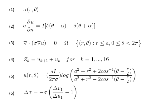
To determine the changes of conductivity (noted by equation (1)) within a circular region from a finite number of voltage measurements on a boundry, a current is applied to parts of the boundary. This then becomes a partial differential equation subject to the boundary conditions as seen in equations (2) and (3). Altogether, this is a boundary value problem (BVP).
This is called an inverse problem because the material properties are determined from measurements of field quantities and in this case, can lead to identifying anomolies such as tumours which are known to have much higher conductivities than normal tissues. Thus, because of this property of tumours, identifying areas of perturbed conductivities can image the tumour!
The data is of simulated voltage measurements along the boundary of a circular region.
Information about the file:
- Contains 128 = 16 X 8 data points representing the voltage differences from 16 nodes.
- The nodes are uniformly distributed along the boundary of the circle.
- Due to symmetry, there are only 8 indepedent axially distributed nodes simulating the pairs k - k'.
- The first of the 16 is along the x axis, aka the phi angle is 0.
- Z1 is the voltage difference between the stimulating axis T1 and the next terminal marked T2.
- Subsequent elements represent the voltage differences as seen as in equation (4).
The solution to the BVP noted by equations (2) and (3) is found to be as shown in equation (5). This is found by using Green's functions.
In order to find the conductivity in the material, equation (6) is implemented using voltage measurements (v) from the Z_data.mat file and the (u) calculated from equation (5).
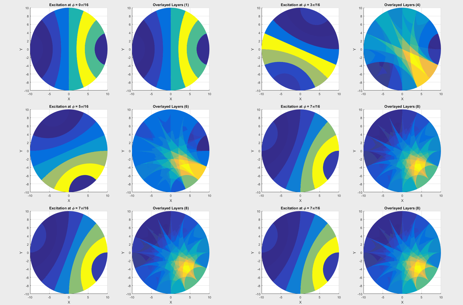
The gif shows the results of the calculated impedances. To the left, it shows us the inidvidual responses from exciting one of the eight axial nodes. In each frame, the yellow shows a high intensity along a strip that the anomaly exists in. As we rotate around the region, we superimpose all these images to get the image on the right of the gif. The superimposed image provides the location of where the anomoly exists within the circular region (all determined by boundary values)!
Trouble viewing the GIF? Download the video here: Video.
The completed EIT scan is the superposition of the 8 axial excitations. The complete code written in MATLAB can be downloaded here: project_eit.m.
The final scan is seen as the gif found at the top of the page!
An image of the equations used are found in the image below:


