Overview
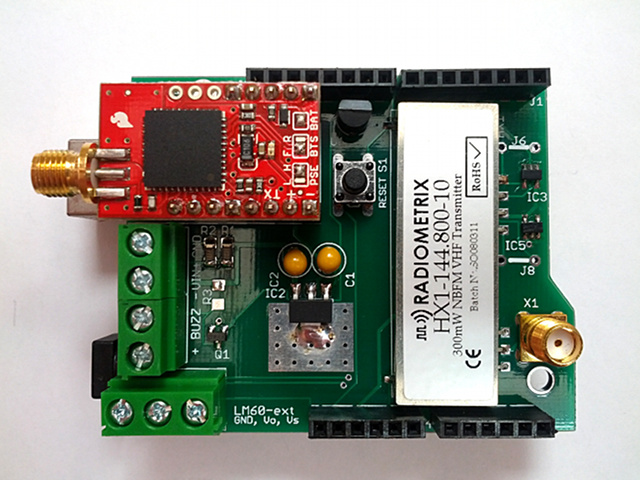
This is how the tracker looks like:
Building the tracker
The latest version of the Trackuino shield is 2.2.
Use the Download ZIP button to get the schematic / pcb files.
You can use the PCB fab house of your preference to have it manufactured. I have been using iteadstudio.com's PCB prototyping service with success so far. The gerber files included in the zip were generated for iteadstudio.
Here is the bill of materials:
| Label | Qty | Component | Provider |
|---|---|---|---|
| C1, C2 | 2 | 10 µF | Mouser |
| GPS | 1 | Venus 638FLPx | Sparkfun (check for local distributors if you want to avoid customs) |
| GPS | 1 | Female headers | Mouser, or Banggood for a lifetime supply. Cut them to desired size. |
| IC2 | 1 | 3.3V LDO regulator | Mouser |
| IC3, IC4, IC5 | 3 | 3-5.5V buffer | Mouser |
| J1, J2, J3, J4 | 1 set | Arduino 6, 8 pin male-female headers | Dealextreme + Dealextreme (5 sets), or Dealextreme (1 set), or Jameco (1 set) |
| J5 | 1 | Pin header | Searching for pin headers in Mouser is a PITA. I suggest buying from Dealextrme or Banggood where you get a lot more for a fraction the price. Also: Jameco |
| M2 | 1 | Radiometrix HX1 | Radiometrix, 144.800 MHz for Europe. The US distributor of the 144.390 MHz version is Lemos International |
| Q1 | 1 | N-channel MOSFET | DMN2050L-7 at Mouser, or similar. If you are looking for alternatives, search for any SOT-23-3 N-channel MOSFET that has a low RDS(on) (around 100 milliohms or less) at a VGS <= 3.3V |
| R1 | 1 | 10K | Mouser |
| R2 | 1 | 3K3 | Mouser |
| R3 | 1 | 1K | Mouser |
| S1 | 1 | Pushbutton | Mouser, or lifetime supply from Dealextreme |
| U1 | 1 (internal) + 1 (external) | LM60 thermometer | Mouser |
| X1 | 1 | Female SMA connector | Mouser, Dealextreme, Banggood |
| X2, X4 | 2 | 2-pin terminal block (screw clamp) | Mouser, Banggood, probably easy to find on Aliexpress, Dealextreme, etc. |
| X3 | 1 | 3-pin terminal block (screw clamp) | Mouser, Dealextreme, ... (same as above) |
Some of the items above can also be found on Digikey (thanks marty.brennan for your contribution). If you're a registered user, you can save this as a .csv and upload:
| Quantity | Part Number | Customer Reference |
|---|---|---|
| 1 | CR1206-FX-1001ELFCT-ND | R3 |
| 1 | CR1206-FX-2211ELFCT-ND | R2 |
| 1 | CR1206-FX-6811ELFCT-ND | R1 |
| 1 | 486-1943-ND | S1 |
| 1 | 277-1578-ND | X3 |
| 2 | 277-1667-ND | X2,X4 |
| 2 | LM60CIZ/NOPB-ND | U1, EXT.LM60 |
| 3 | M74VHC1GT125DT1GOSCT-ND | IC3-IC5 |
| 2 | 478-1839-ND | C1,C2 |
| 1 | 568-7534-1-ND | Q1 |
| 1 | 991-1046-ND | X1 |
| 1 | AP1117E33GDICT-ND | IC2 |
In addition to the above, you need:
- GPS antenna from Dealextreme. Mouser also carries SMA GPS antennas if you think DX is too slow. Make sure the connector is the SMA male type. Read the SMA-connectors page for clarification on the SMA/RPSMA/male/female nomenclature. Even though the DX description says "F cable", it's actually a male SMA, but doublecheck before buying.
- VHF (144 MHz) antenna. A DIY 1/4 wave groundplane (with radials) is the most effective.
Power
There are 3 ways to power the tracker. In either case, the recommended voltage is 7..12 VDC:
- Using the Arduino barrel jack, or...
- Using the VIN and GND clamp terminals (next to the GPS module).
- Using a USB cable plugged to a host computer. This will work because of the reverse current diode built in the 5V regulator, which will provide enough voltage to power the shield's 3.3V regulator.
Power usage for a 7.5 VDC reference voltage is:
| Status | Current |
|---|---|
| Waiting for GPS fix | 120 mA |
| Normal operation (idle) | 70 mA |
| Normal operation (HX1 transmitting) | 200 mA |
Buzzer
There are two kinds of buzzers:
- Active (aka DC) buzzers and
- Passive (aka AC) buzzers
The fundamental difference is that active buzzers take a direct current (DC) voltage whereas passive buzzers are driven by a square wave. DC buzzers have an internal oscillator that translates DC into a fixed-frequency square wave, which is then used to drive the piezoelectric membrane. An AC buzzer, on the other hand, needs that square wave to be generated externally and thus its frequency can be controlled.
The Trackuino shield can use both kinds of buzzers:
- If you use an active (DC) buzzer:
- Do not solder
R3 - In config.h, set BUZZER_TYPE to 0.
- DC buzzers have a fixed frequency, so BUZZER_FREQ won't matter.
- Do not solder
- If you use a passive (AC) buzzer:
- Do solder
R3. Piezo buzzers behave as capacitors and when the fet is off they need a path to discharge and relax. Because of this bleeder resistor, the buzzer won't sound as loud as if it was driven by a push-pull buffer, but it keeps things simpler. - In config.h, set BUZZER_TYPE to 1.
- Set BUZZER_FREQ to the desired frequency in Hertz.
- Do solder
What's with the jumpers?
J5
When shorted, this jumper connects the Arduino TX pin with the GPS RX pin so that the MCU can send commands to the GPS, but then you can't print any debug information out the serial port and into the Arduino IDE's console.
When open, you can print debug info from the firmware and it will be displayed on the Arduino IDE's console, but you can't send commands to the GPS.
I suggest soldering a two pin male header on J5, or just leaving it unpopulated, since the GPS doesn't need any special command from the firmware to operate normally, whereas debug information can be useful when hacking or diagnosing the firmware.
J6, J7, J8
Since shield version 2.1, the board can talk to both 5V and 3.3V microcontrollers, so you can plug the board into a 5V Arduino as well as 3.3V compatible devboards like the Chipkit Uno32. The shield uses 74*125 buffers that work as 3.3/5V level converters. The HX1 module uses 5V logic and the Venus GPS uses 3.3V logic, so no matter what the logic of your MCU is, some conversion needs to be done:
- If your MCU is 5V (Arduino Duemilanove, Uno): IC4 needs to be soldered and J6, J8 need to be shorted. IC4 provides the 5->3.3V downconversion for the GPS.
- If your MCU is 3.3V (Chipkit Uno32): IC3, IC5 need to be soldered and J7 needs to be shorted. IC3 and IC5 provide the 3.3V->5V conversion for the two HX1 inputs.
I suggest to solder all three buffers (IC3, IC4 and IC5) and none of the bridges (J6, J7, J8), then you will have a board that is compatible with both 5V and 3.3V logics.
Caution
Things you should pay special attention to:
- First and foremost, do not turn on the tracker without a proper antenna!! Power not radiated by the HX1 will reflect back and cause overheating that might eventually fry the HX1 and/or the whole board.
- Be careful when you plug the shield. It's relatively easy to misalign the headers and leave one or more pins outside the sockets.
- If you use an external LM60, make sure it's connected properly. Here is the LM60 datasheet. For a quick test, you can spread out the pins of the chip and connect it directly to the terminal blocks, with its flat side facing up.
Building the firmware
The recommended version of the firmware is Trackuino 1.51. Check that page for downloading and building directions.
Testing
Refer to Troubleshooting if something doesn't work the way it should.