Maverick Flight Code

Text Version
Maverick Flight Computer
Components and Construction
The Basics
- Double-Sided PCB Board
- 22AWG Solid Core Wire
- 60/40 Rosin Core 0.5mm Solder Wire
- 1/2" Kapton Tape
- Non-Static Sponge
The Main Processor
For this project, I decided to use a Teensy 4.1. The large amount of pins, combined with the beefy processing power and the on-board SD card reader was the winning combo.
Communication Sensors
- Radio: Adafruit RFM69HCW Transceiver Radio Breakout 433 MHz
- GPS: Adafruit Ultimate GPS Breakout
- SD Card: 32GB
Sensors Continued...
- NeoPixel Ring - 12 x 5050 RGB LED
- Piezo Transducer - 15V Buzzer
- ADXL377 - High-G Triple-Axis Accelerometer
- MS5611 High Resolution Atmospheric Pressure Module
It's Got The Power!
To power the on-board computer, a 3.7V LP963450 1800mAh battery was connected to a PowerBoost 1000 Basic 5V USB Boost via a USB to MicroUSB cable to the Teensy MicroUSB port.
And Finally, the Ground Computer
The Ground Computer was a much simpler set-up, made up of an Arduino Uno and an Adafruit RFM69HCW Transceiver, connected via a breadboard and connected to a laptop.
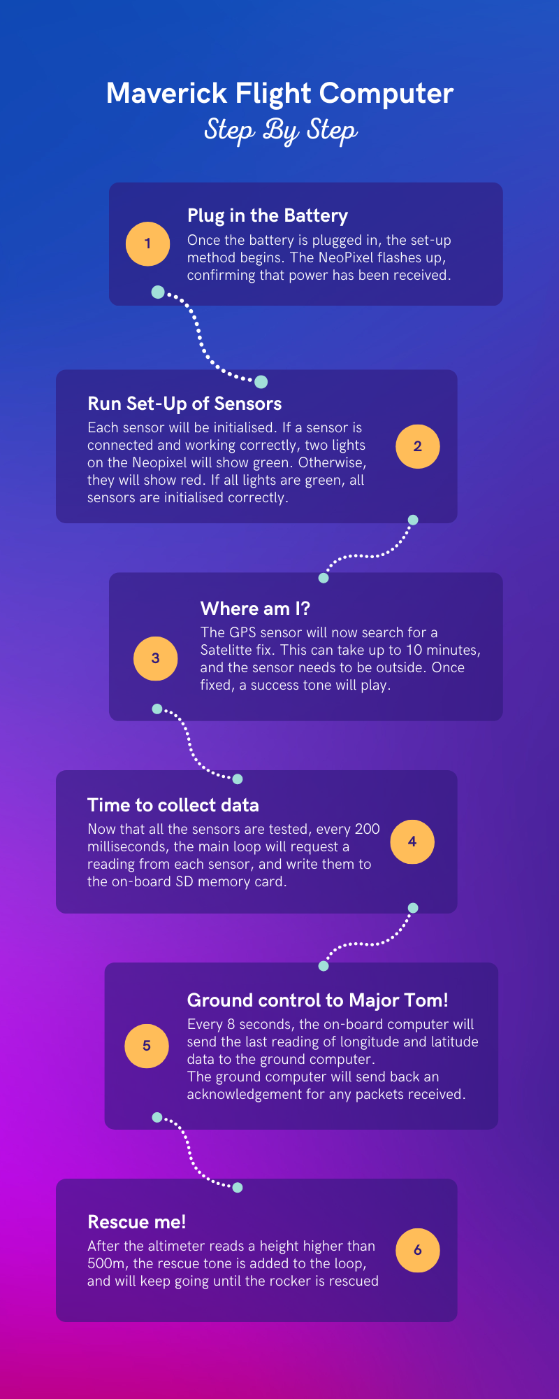
Maverick Flight Computer
Step by Step
-
Plug in the Battery
Once the battery is plugged in, the set-up method begins. The NeoPixel flashes up, confirming that power has been received.
-
Run Set-Up of Sensors
Each sensor will be initialised. If a sensor is connected and working correctly, two lights on the Neopixel will show green. Otherwise, they will show red. If all lights are green, all sensors are initialised correctly.
-
Where am I?
The GPS sensor will now search for a Satelitte fix. This can take up to 10 minutes, and the sensor needs to be outside. Once fixed, a success tone will play.
-
Time to collect data
Now that all the sensors are tested, every 200 milliseconds, the main loop will request a reading from each sensor, and write them to the on-board SD memory card.
-
Ground control to Major Tom!
Every 8 seconds, the on-board computer will send the last reading of longitude and latitude data to the ground computer.
The ground computer will send back an acknowledgement for any packets received.
-
Rescue me!
After the altimeter reads a height higher than 500m, the rescue tone is added to the loop, and will keep going until the rocker is rescued