Amiga_DB23_video_adapter
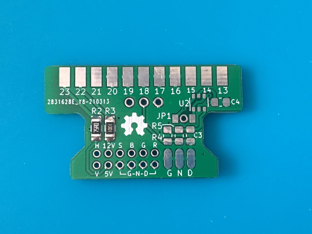
A PCB for creating Amiga DB23 to SCART or Amiga DB23 to VGA cables. You can use this adapter to feed a new clock for the Amiga via XCLK (pin 1). The XCLK provides a new base frequency for the entire Amiga, since that all clocks are a multiplier of the color clock frequency, be it NTSC or PAL. The Amiga Agnus chip derives all clocks in the machine (CCK, CCKQ, 7M, /CDAC, 14M) from the main 28M crystal oscillator.
Why use this adapter with XCLK?
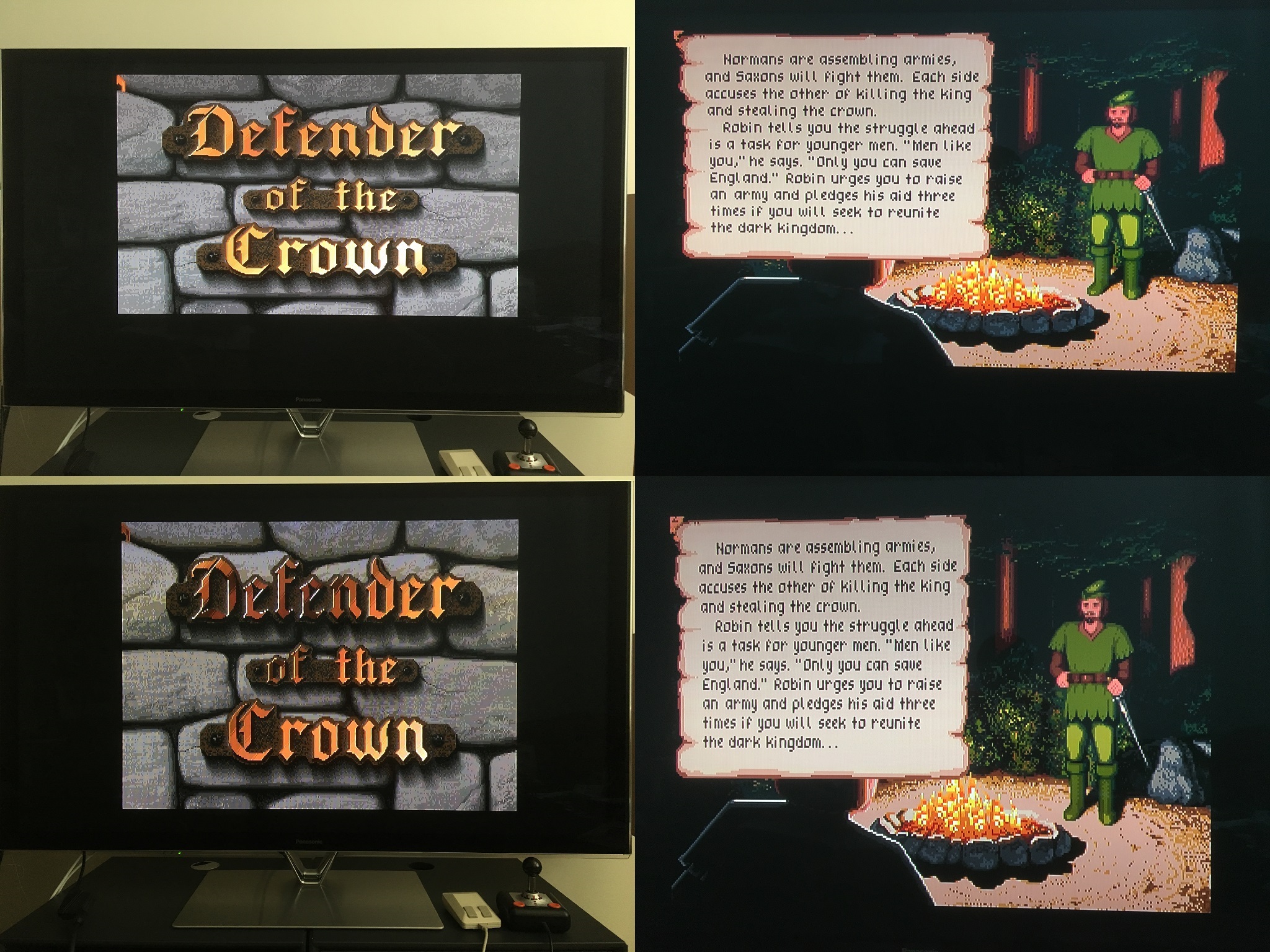
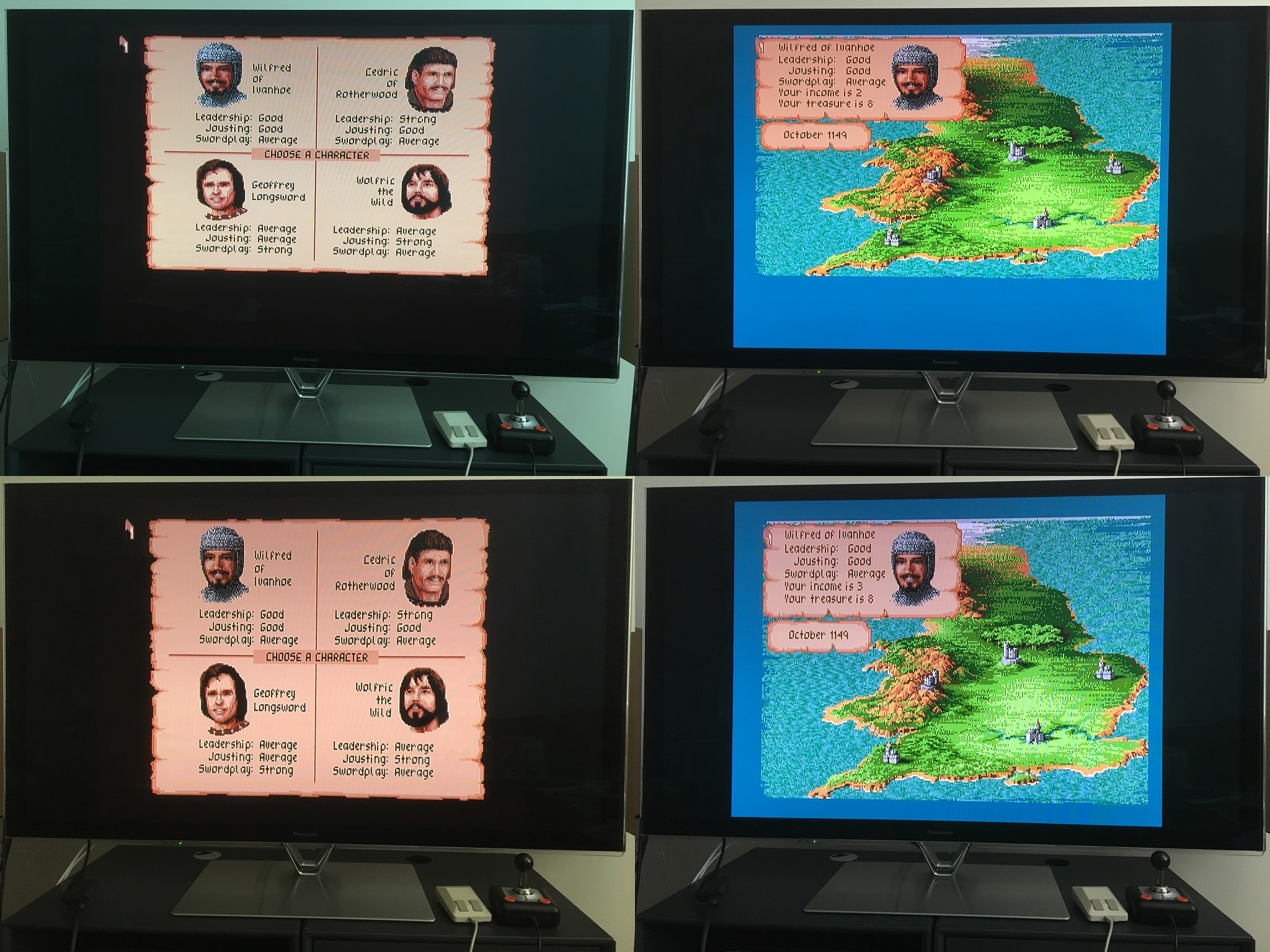
You don't have to, but being able to switch between true native PAL and true native NTSC in one machine is a very nice feature to get the correct aspect ratio on game graphics, also correct speed for sound playback and gameplay with smooth scrolling in both PAL 50 Hz and NTSC 60 Hz. For example check the comparison below on the game Defender Of The Crown with the awesome graphics, by the artist Jim Sachs, looks so much better in NTSC (lower pics). In PAL mode everything looks kind of squashed.
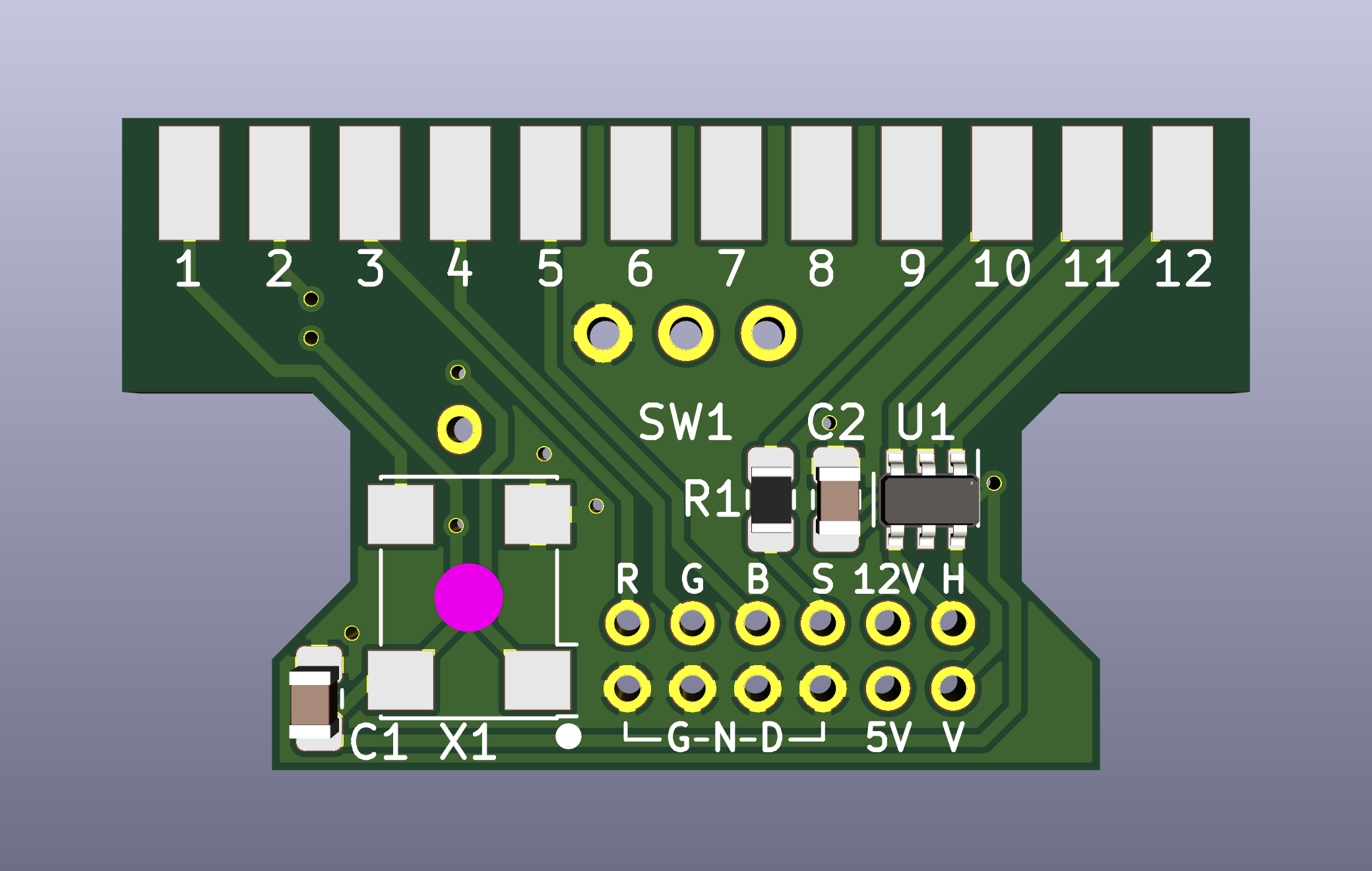
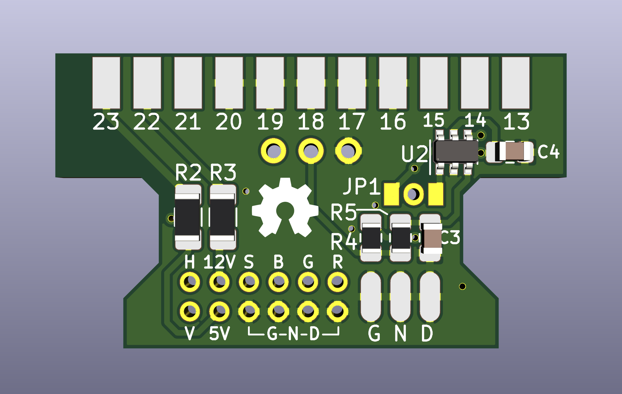
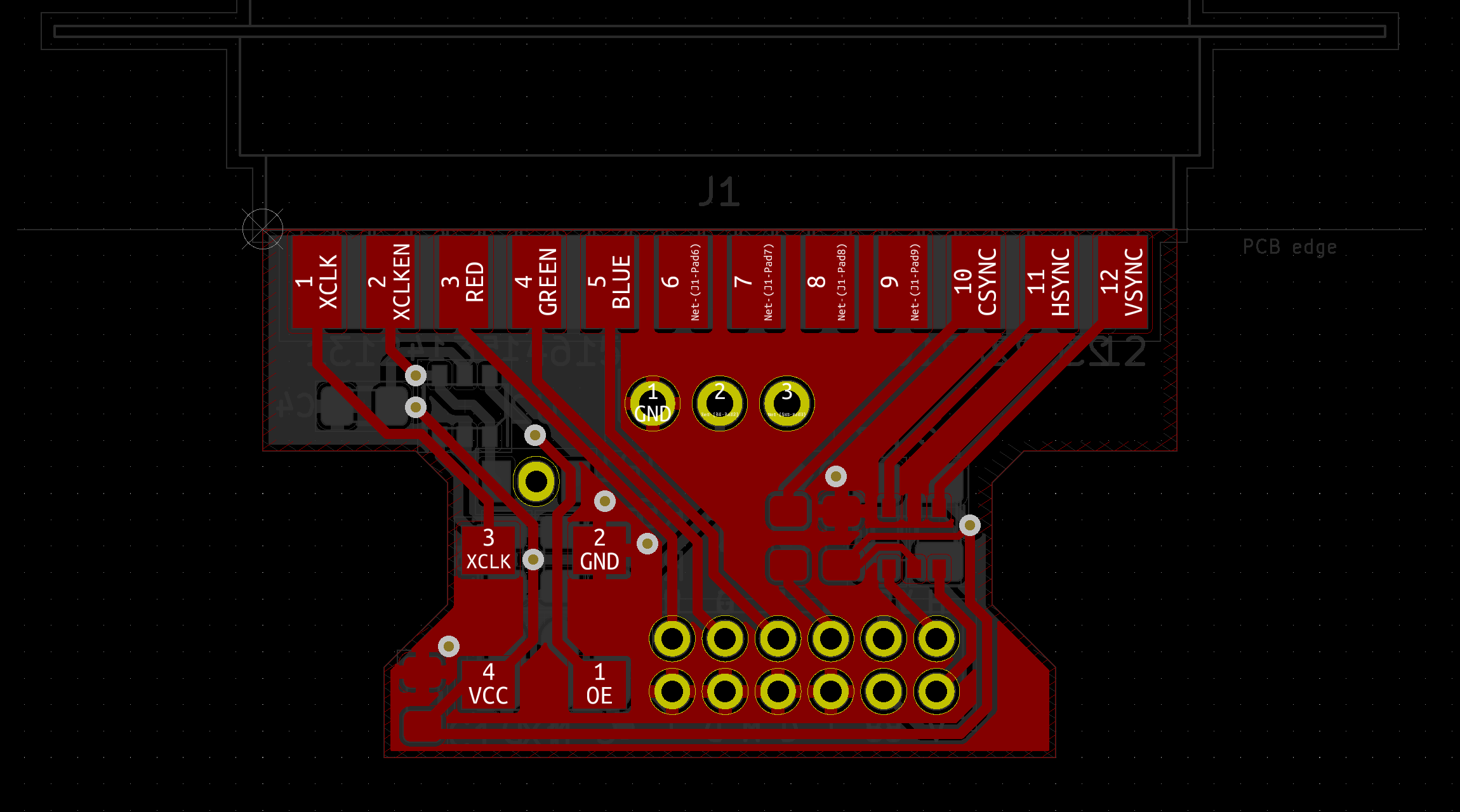
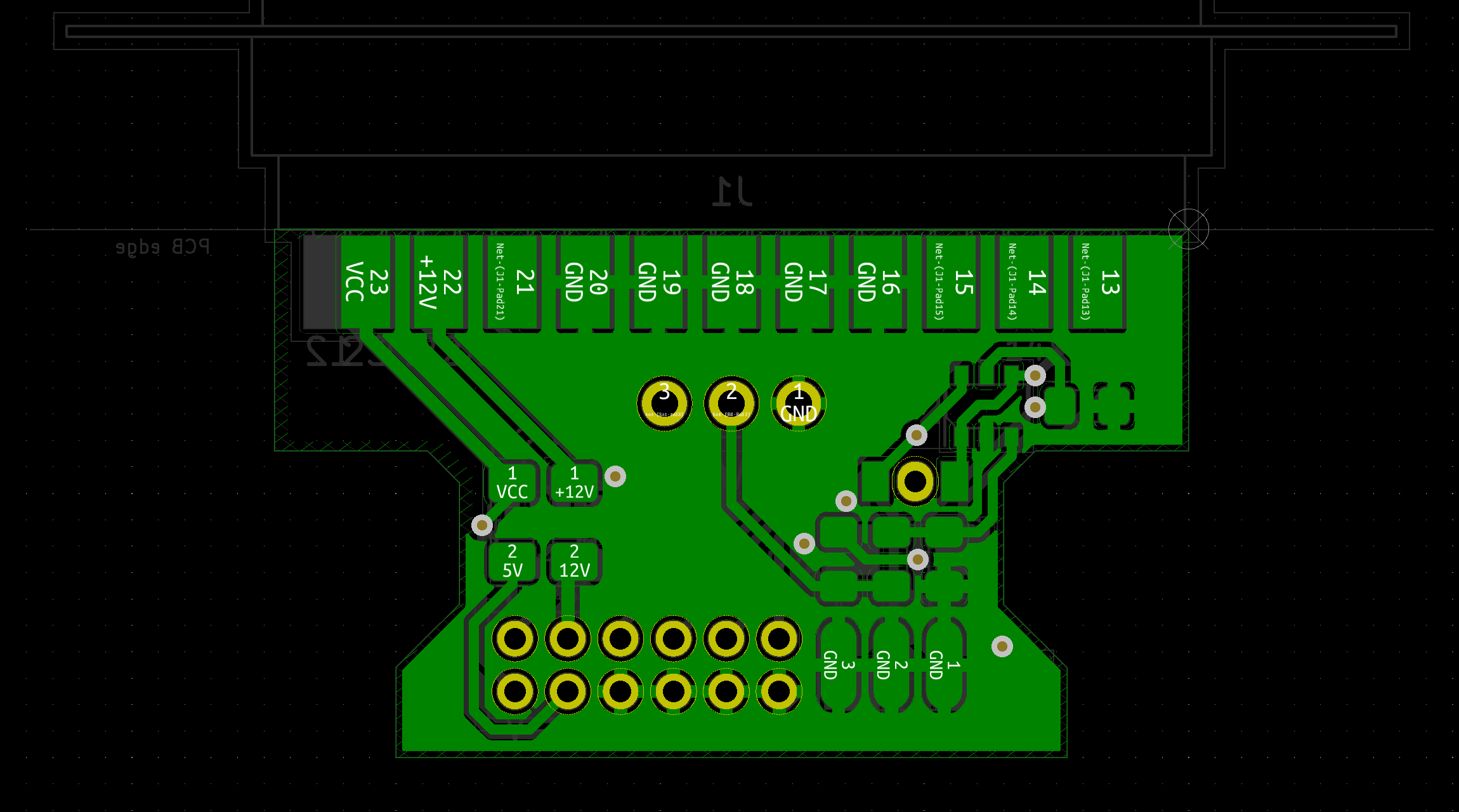
The HSync and VSync lines are buffered via a dual non-inverting Schmitt-trigger IC to reduce jitter and noise. The PAL/NTSC switch has a simple resistor-capacitor (RC) debounce circuit using the hysteresis in a dual-inverting Schmitt-trigger IC for proper debounce in hardware. This IC also controls the enabling (OE-pin) of the crystal oscillator as well as asserting the /XCLKEN line (pin 2). A solderpad with a jumper-pin exists for connecting a jumper-wire back to a switchable Agnus (Not all Agnuses are switchable) on pin 41 (or JP4 on A500 Rev. 6A), this is completely optional, check your Agnus version before trying such a mod and that JP4 isn't bridged to GND. All ECS Agnuses can be switched in Software should your Agnus not have the PAL/NTSC pin. KS 3.0 and above lets you switch in early startup menu that you can access by holding down the two mouse buttons right after resetting the machine.
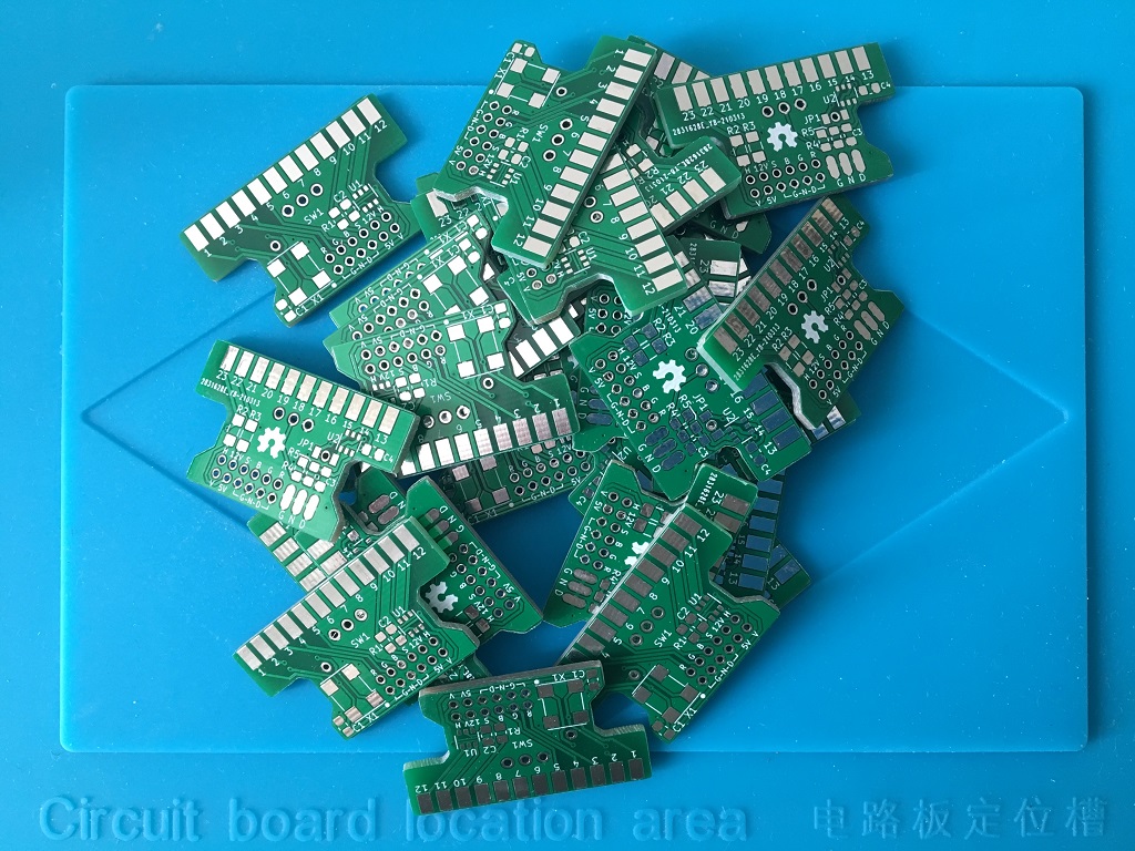
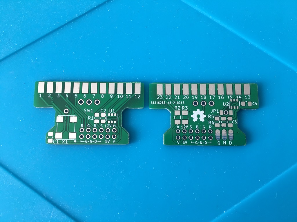
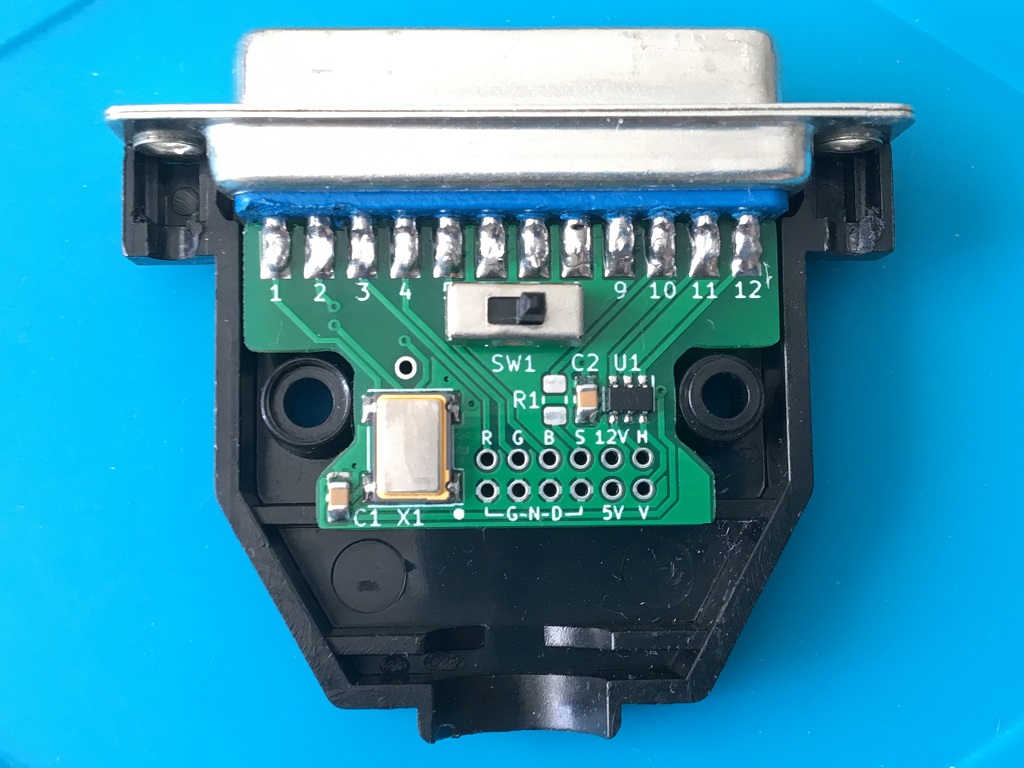
With this adapter you can:
1. Make an Amiga DB23 to SCART RGBS (RGB with CSync) cable,
   and optionally populate X1 with either a 28.63636 MHz (NTSC)
   or 28.37516 MHz (PAL) oscillator, obviously you'll choose a crystal here
   opposite to what your machine has on the motherboard.

or

2. Make an Amiga DB23 to VGA RGBHV (RGB with separate HSync, VSync) cable
   (This requires a 15 kHz compatible monitor http://15khz.wikidot.com/ ),
   and optionally populate X1 with either a 28.63636 MHz (NTSC)
   or 28.37516 MHz (PAL) oscillator, obviously you'll choose a crystal here
   opposite to what your machine has on the motherboard.

or

3. Make a Plug-only with no cable and populate X1 with either a 28.63636 MHz (NTSC)
   or 28.37516 MHz (PAL) oscillator, obviously you'll choose a crystal here
   opposite to what your machine has on the motherboard. I assume you're using RGB2HDMI
   or similar for hooking up your display but still want to be able to switch between true
   PAL/NTSC by feeding XCLK to the machine.
If you use jumper-wire from JP1-pin then you bridge it either with the left pad or the right pad depending on your setup:
1. Motherboard has PAL oscillator and Adapter has NTSC oscillator = bridge JP1-pin with XCLKEN-pad
2. Motherboard has NTSC oscillator and Adapter has PAL oscillator = bridge JP1-pin with OE-pad
Please note, using a jumper-wire is completely optional, You can switch ECS Agnus in Early Startup menu or with software such as Degrader and then ju only switch the external XLCK-crystal enable or disable via the switch on the cable plug. However it can be more convenient to have both tasks controlled from one single switch, hence connecting a jumper-wire.
BOM SCART
| PART | Value | Description |
|---|---|---|
| R1 | 330 Ohm | 0805 (CSync), to Pin 20 of SCART, (Comp Video In, 1V including sync) |
| R2 | 75 Ohm | 1206 (+5V), to Pin 16 of SCART, High (1-3V) RGB, Low (0-0.4V) Composite |
| R3 | 1k Ohm | 1206 (+12V), to Pin 8 of SCART, Autoselect switch: High (9.5-12V) AVmode, Low (0-2V) TVmode |
I used the Resistor-values following Stedy's guide here:
The Ultimate SCART cable
http://ianstedman.co.uk/amiga-scart-guide/
BOM VGA
| PART | Value | Description |
|---|---|---|
| U1 | 74HCT2G17 | TSOP-6 (Dual non-inverting Schmitt trigger), (HSync, VSync) https://assets.nexperia.com/documents/data-sheet/74HC_HCT2G17.pdf |
| C2 | 0.1 uF | 0805 |
BOM XCLK
| PART | Value | Description |
|---|---|---|
| R4 | 10k Ohm | 0805 |
| R5 | 10k Ohm | 0805 |
| C1 | 0.1 uF | 0805 |
| C3 | 0.1 uF | 0805 |
| C4 | 0.1 uF | 0805 |
| U2 | 74HCT2G14 | TSOP-6 (Dual inverting Schmitt trigger) https://assets.nexperia.com/documents/data-sheet/74HC_HCT2G14.pdf |
| X1 (PAL) | 28.375 MHz | Standard Clock Oscillator 5V (7.5 mm x 5 mm) LFSPXO014117Bulk https://eu.mouser.com/datasheet/2/741/LFSPXO014117Bulk-983232.pdf 91 pcs In Stock at the time of writing |
| X1 (NTSC) | 28.6363 MHz | XO (Standard) CMOS Oscillator 5V (7 mm x 5 mm) K50-HC0CSE28.6363MR https://media.digikey.com/pdf/Data%20Sheets/AVX%20PDFs/K50-HC%20Series%20Oscillators.pdf 895 pcs In Stock at the time of writing |
| JP1 | Solder Jumper with pin for a flylead back to switchable Agnus pin 41 (or its pad on motherboard, e.g. JP4 on A500 Rev.6A) | |
| SW1 | Handle length: 3mm-6mm | On-Off mini slide switch SS12D00 3pin 1P2T 2 Position toggle switch |
Howto modify a vga-cable and use with this adapter
First do some soldering, standard stuff nothing special:
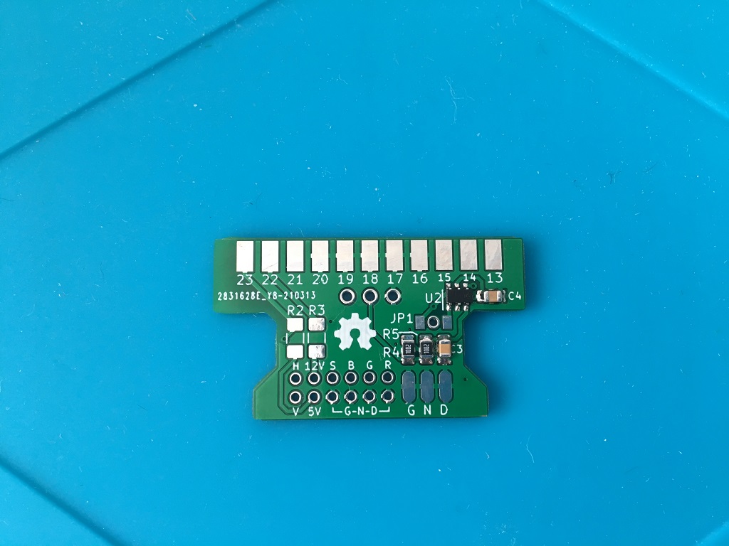
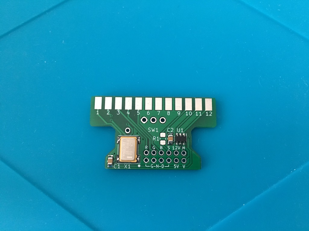
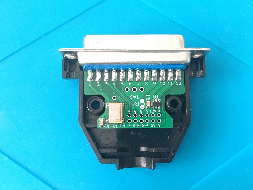
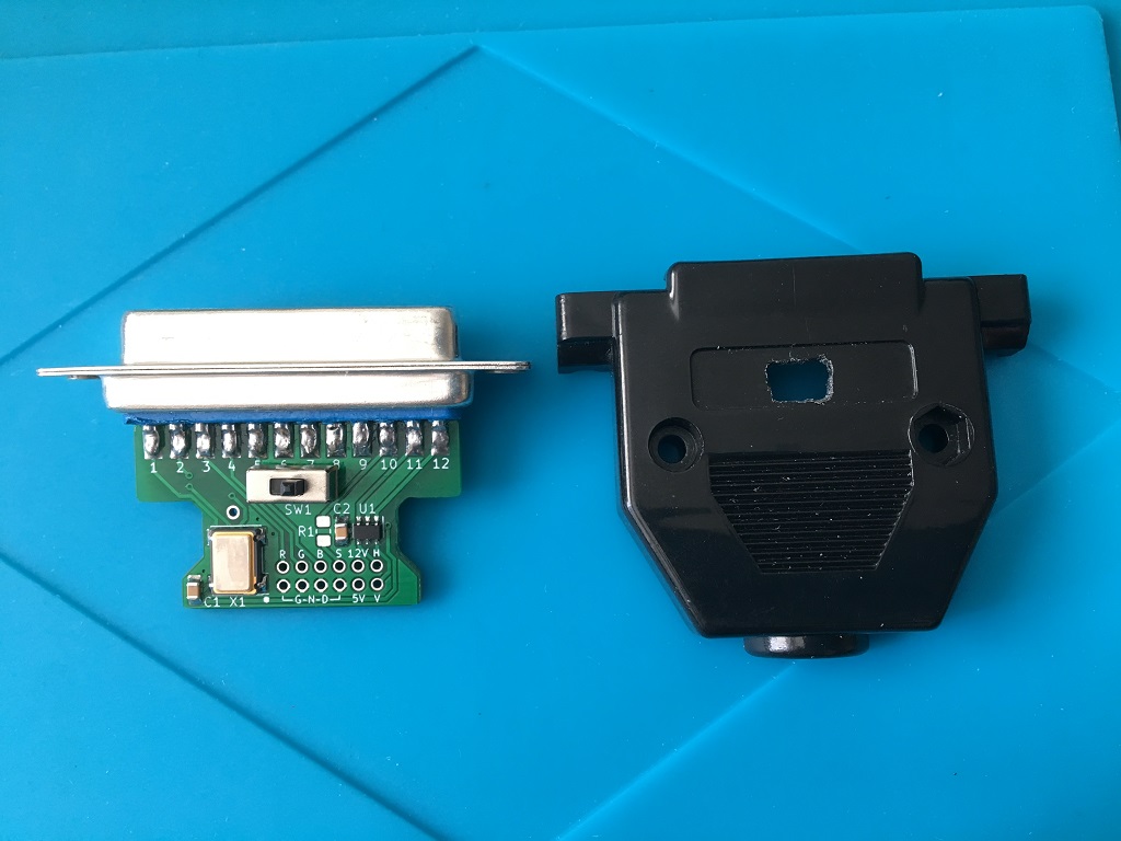
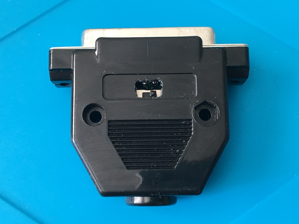
Ok good, now the switch, solder it on and make a hole in the plastic hood (several small drill holes will do, or one 5 mm bulls-eye drill hole.):

Now time to butcher one side of the vga cable:
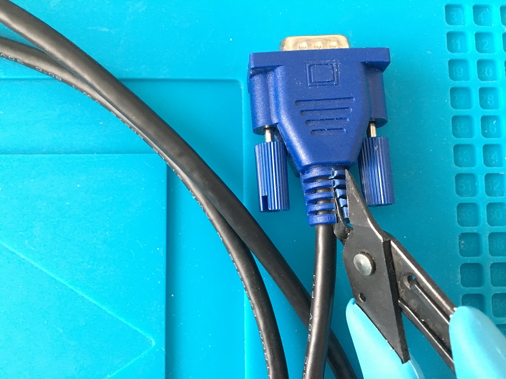
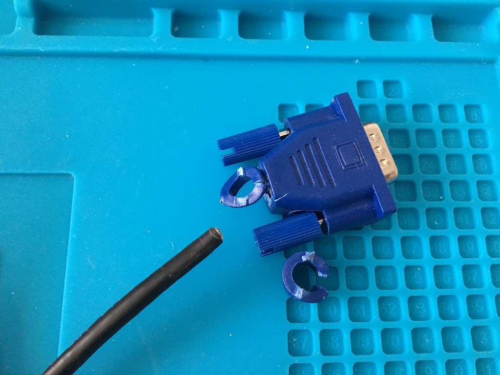
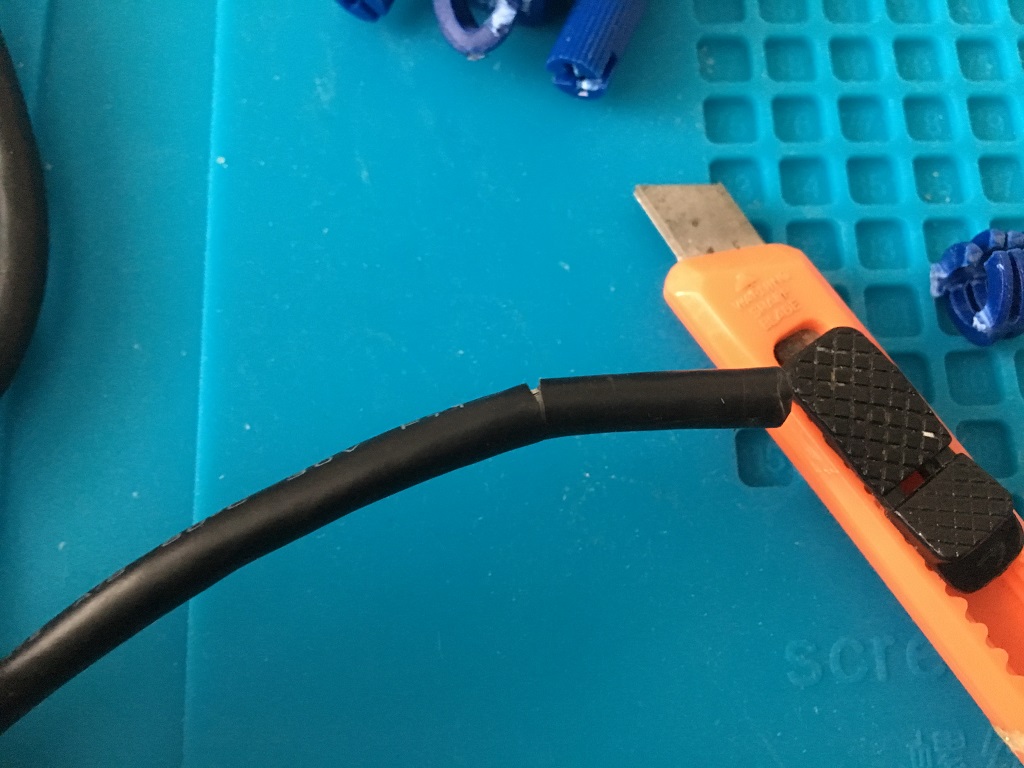
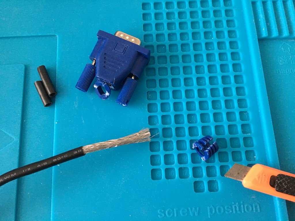
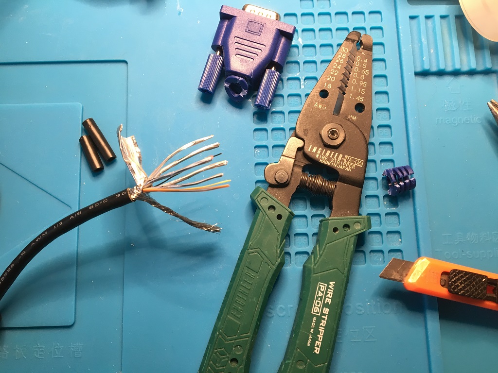
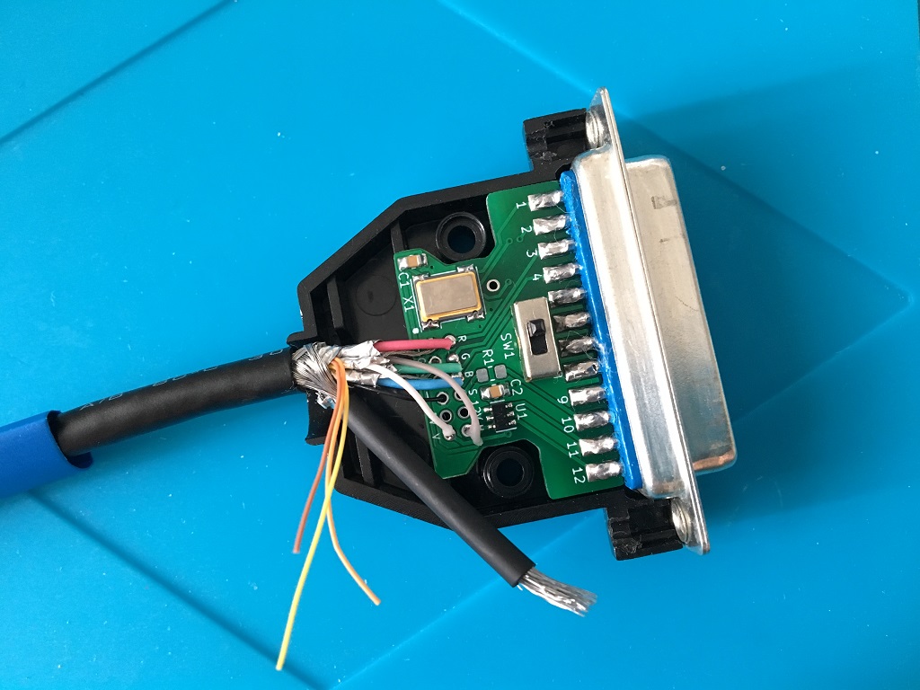
Now, first thing first, put a larger shrink tube around the cable (blue in picture) and then start cutting and stripping wires, you can beep out which one is which. In this cable all the individually shielded wires were RGBHV. Wire together the cable shielding like in picture below and use a shrink tube around. Pic below says it all:
Optional flylead:
Now add a jumper wire with a right angled pin (crimped or soldered to the wire) and solder it onto JP1 bridging it with either of the pads (which one depends on your setup).
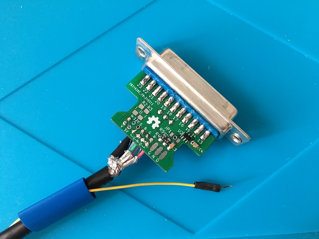
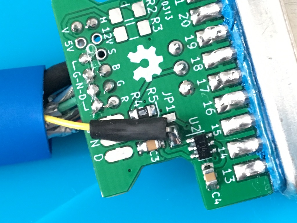
Now, solder the shielding to the metal casing, I first tried without crimping a pin on there but couldn't get a good joint. I used my desolder gun 80W giving enough juice/heat to be able to solder this one finally:
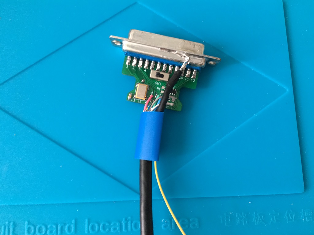
Ok, now heat the blue shrink tube and fit the cable stop, don't tighten too hard.
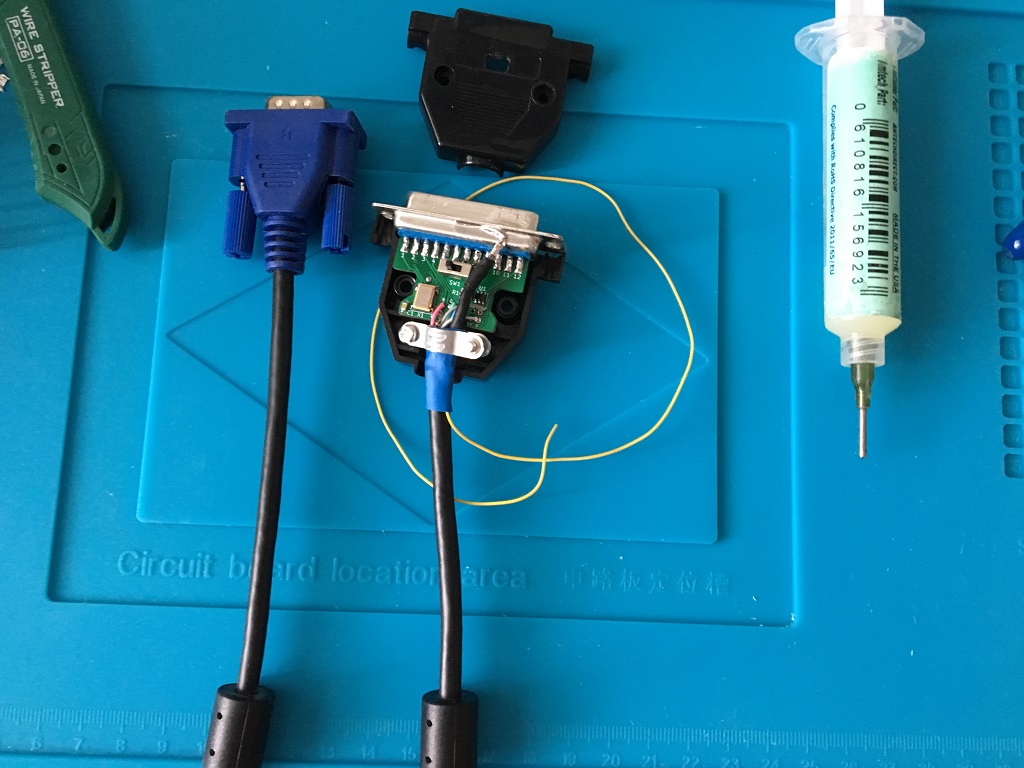
I did some testing that the switch works, and also I beeped out the cable verifying no shorts exists before trying it:
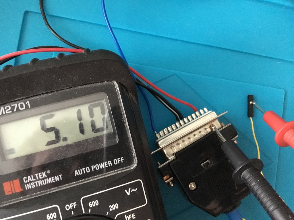
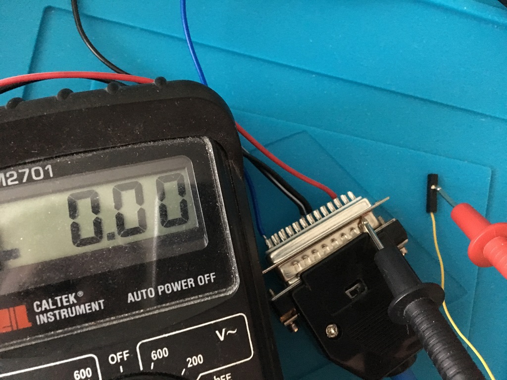
Installing jumper wire in A500 Rev 6A:
I ran the jumper wire through an existing hole in the Amiga 500 case/motherboard, then just soldered it onto JP4 pad next to Agnus verifying no continuity to GND-pad:
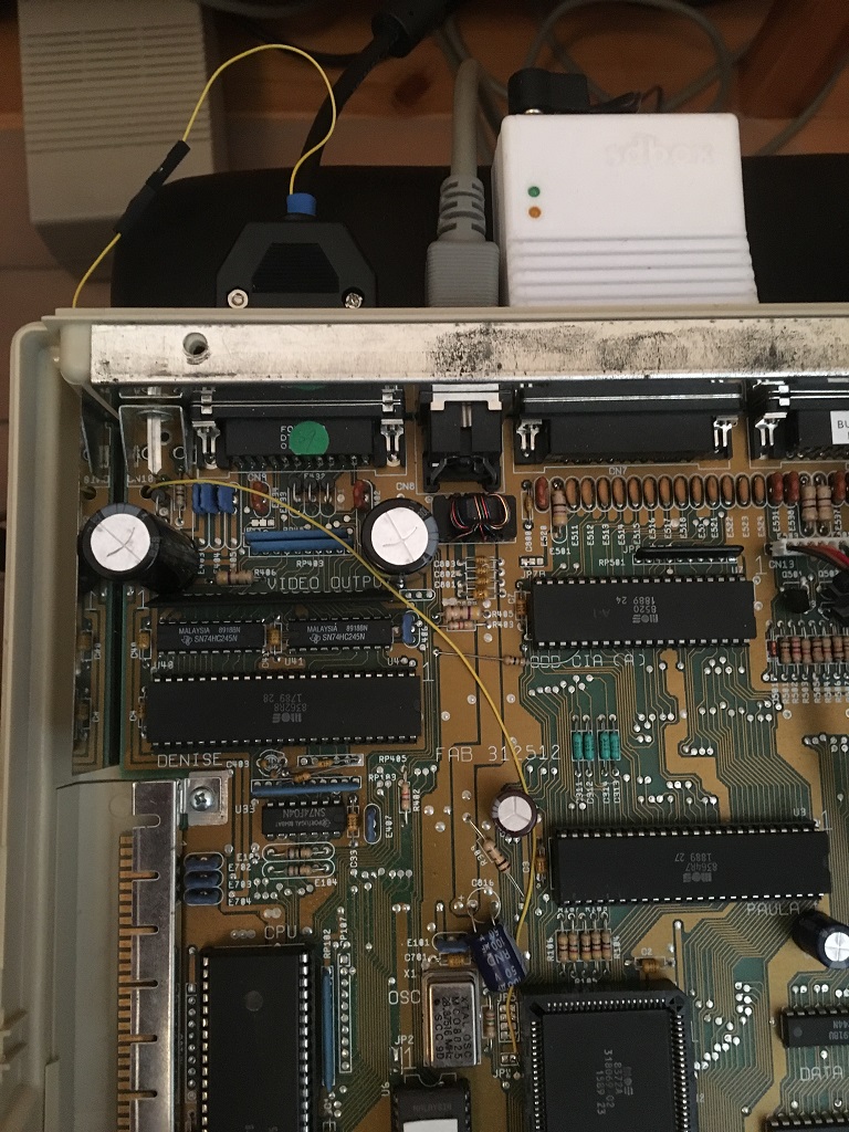
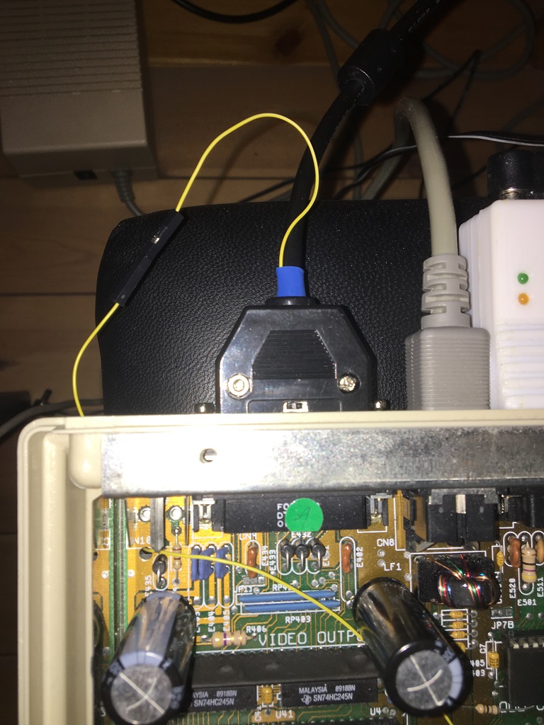
All done! We can now switch between true PAL/NTSC and get correct display resolution, yay!
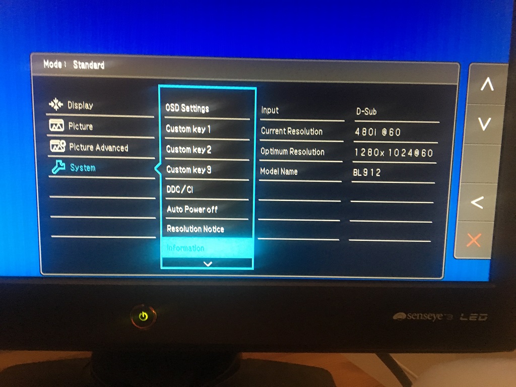
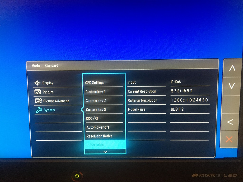
We can even switch during run-time thanks to the proper debounce circuit in hardware, but I think it's best to power off the Amiga, do the switching, and then power on again.
Short video-clip below showing hot-switching, don't try this at home folks ;)
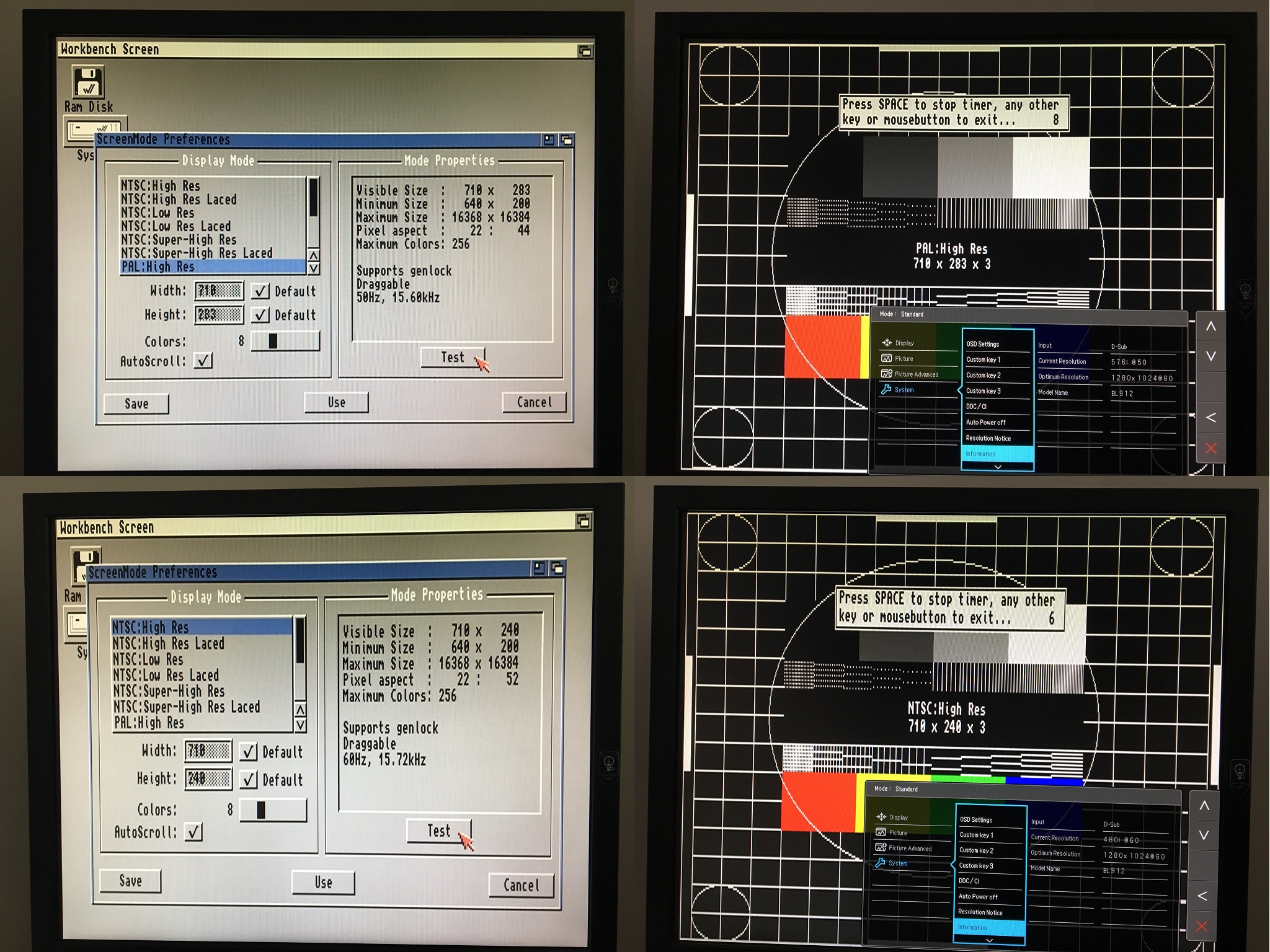
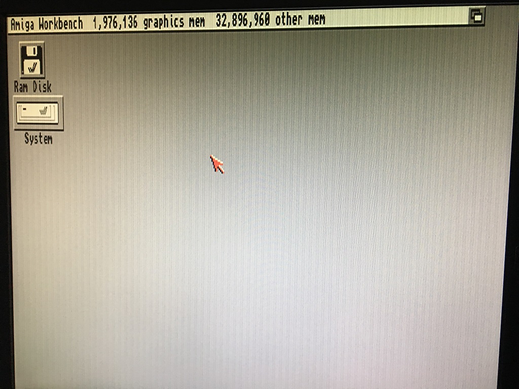
Here a comparison between PAL vs NTSC on WB 3.1.4 on a A1200 and a Benq BL912 tweaked with pixelclock setting around 90 and some overscan, very nice picture quality I must say:
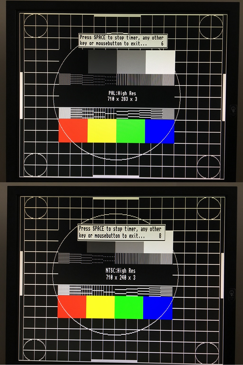
It is very important to adjust the pixelclock on the Benq monitor to get rid of those vertical jailbars, otherwise it will look like this:
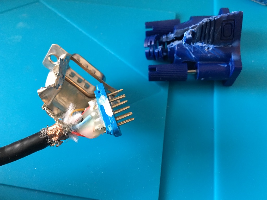
If you ever wondered how one of those moulded vga plugs looks like inside, this is it:
Howto solder a SCART-cable (RGBS) with this adapter.
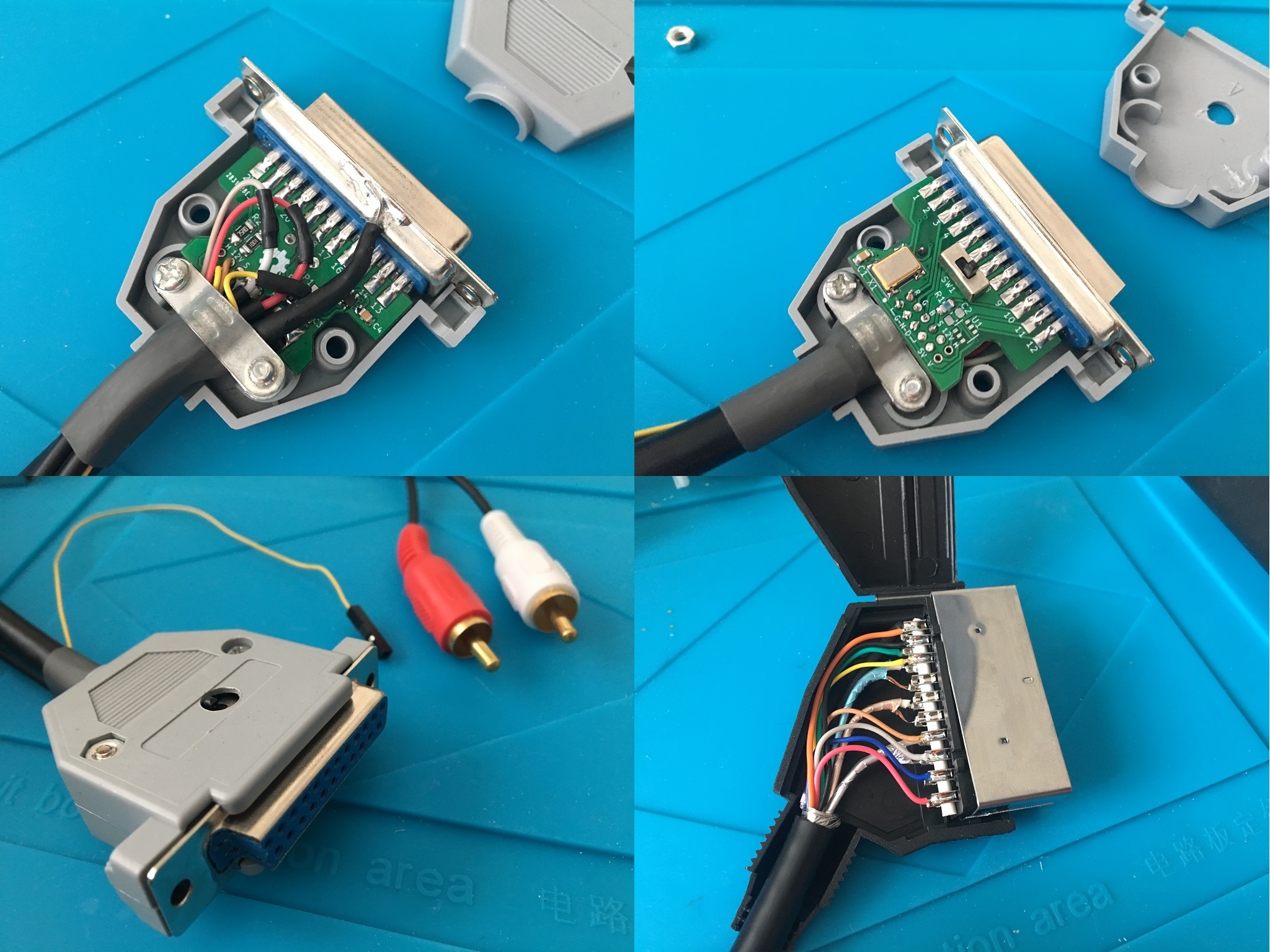
First the resistors R1-R3 and then the oscillator with its decoupling cap:
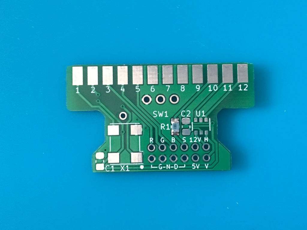
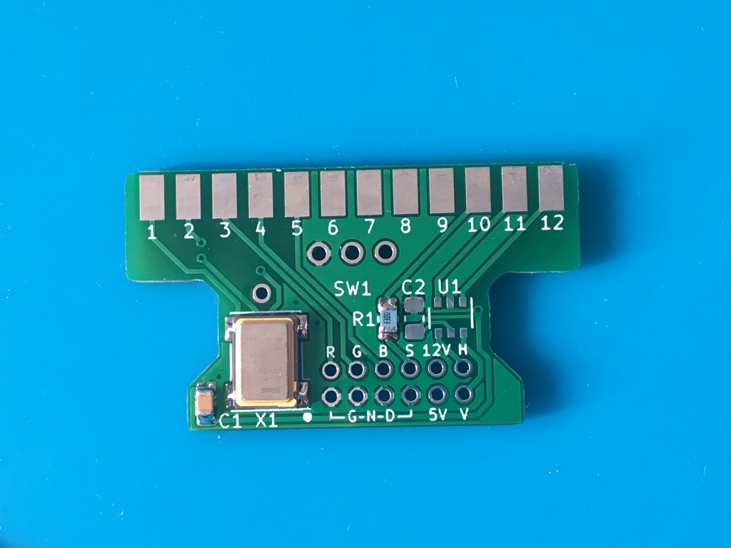
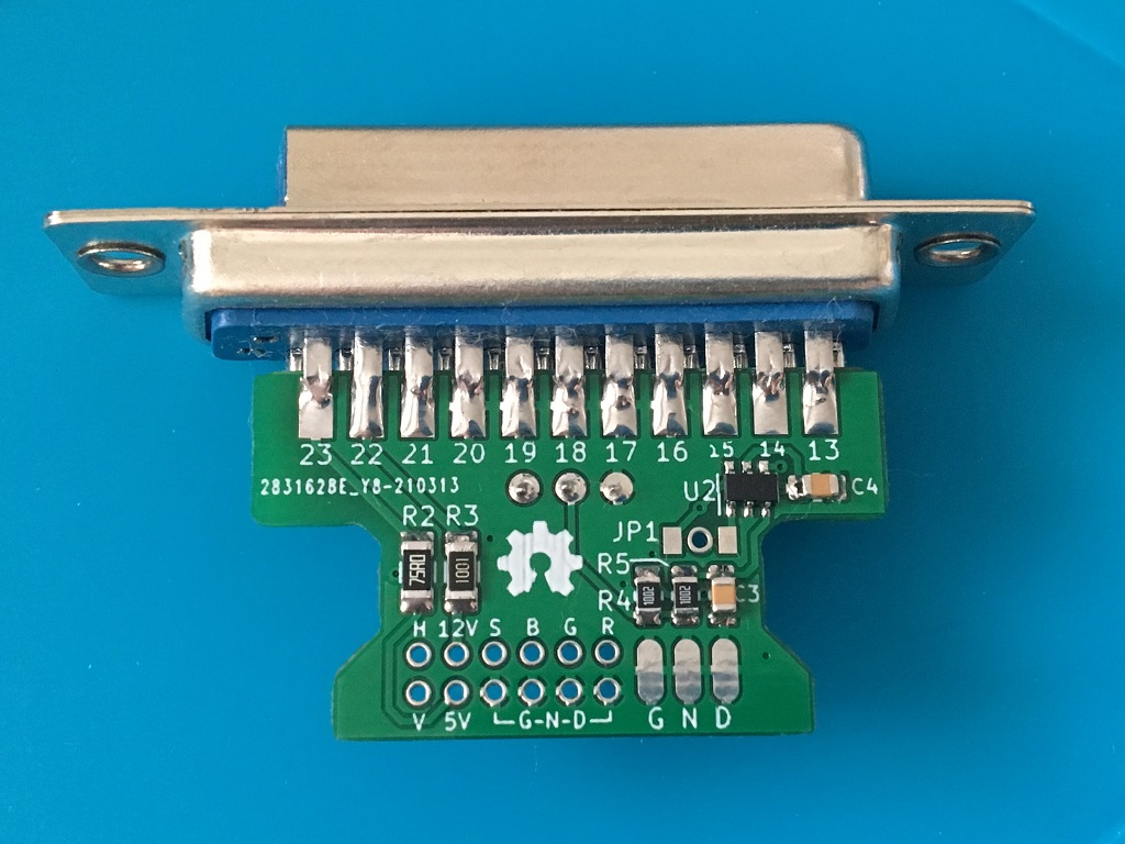
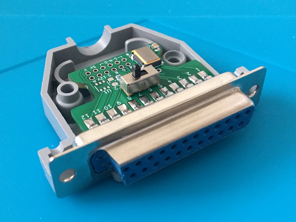
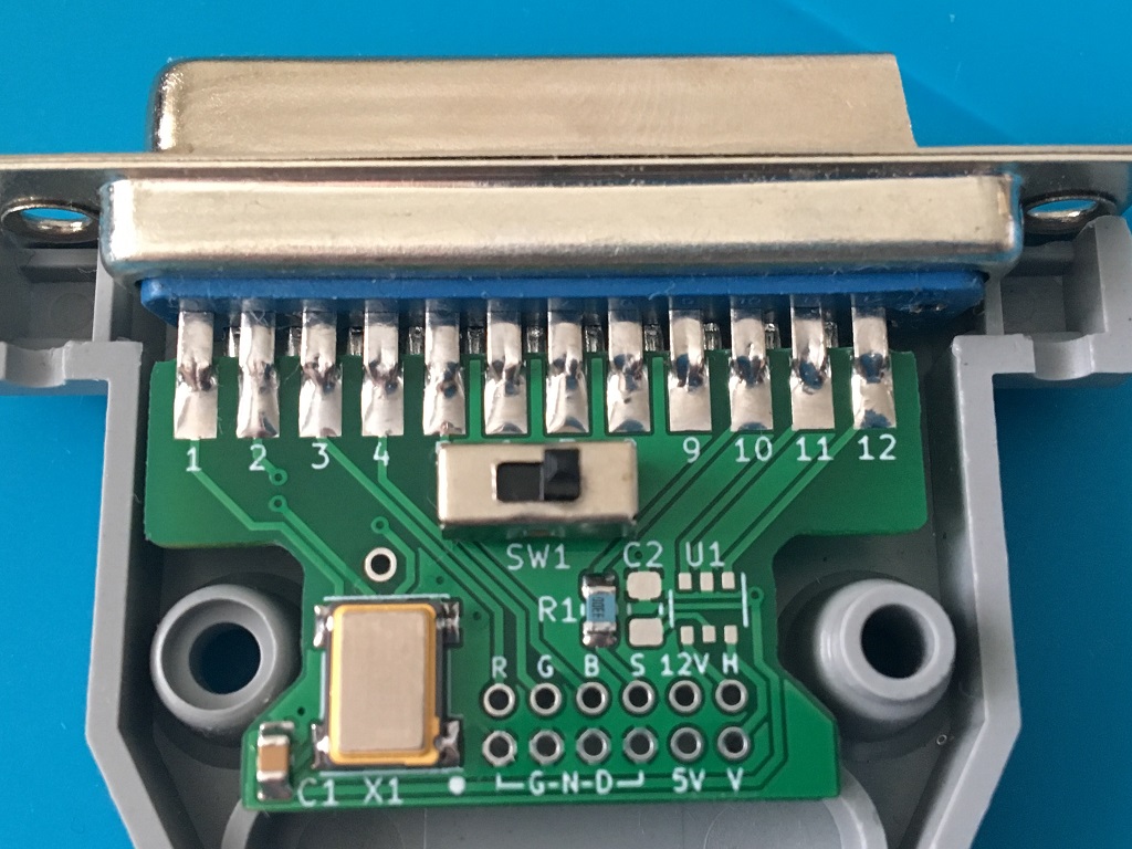
I'm using a cut-down DB25 to DB23 here and because of this I didn't solder the PCB flush against the connector as you would normally do, this is to make the PCB fit in the slighly larger plastic shroud of the DB25. Solder the mini-slide switch as the last step after the 23-pins for easier soldering:
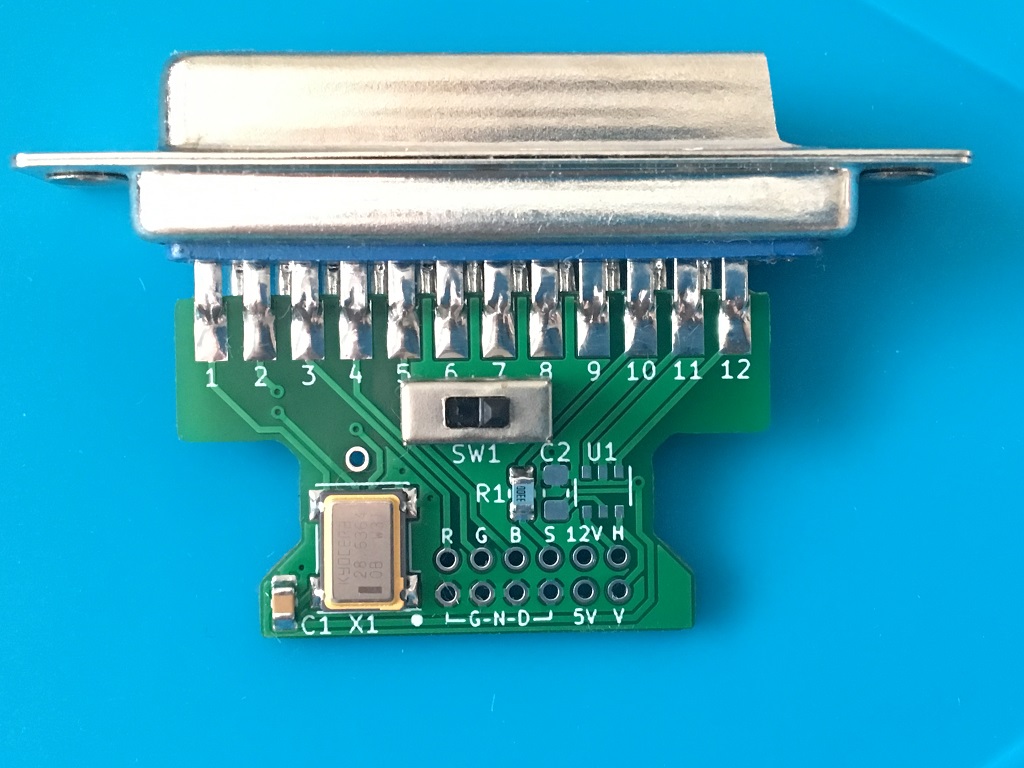
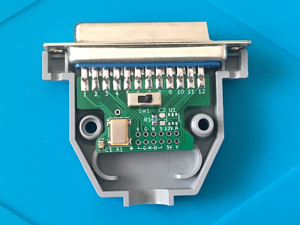
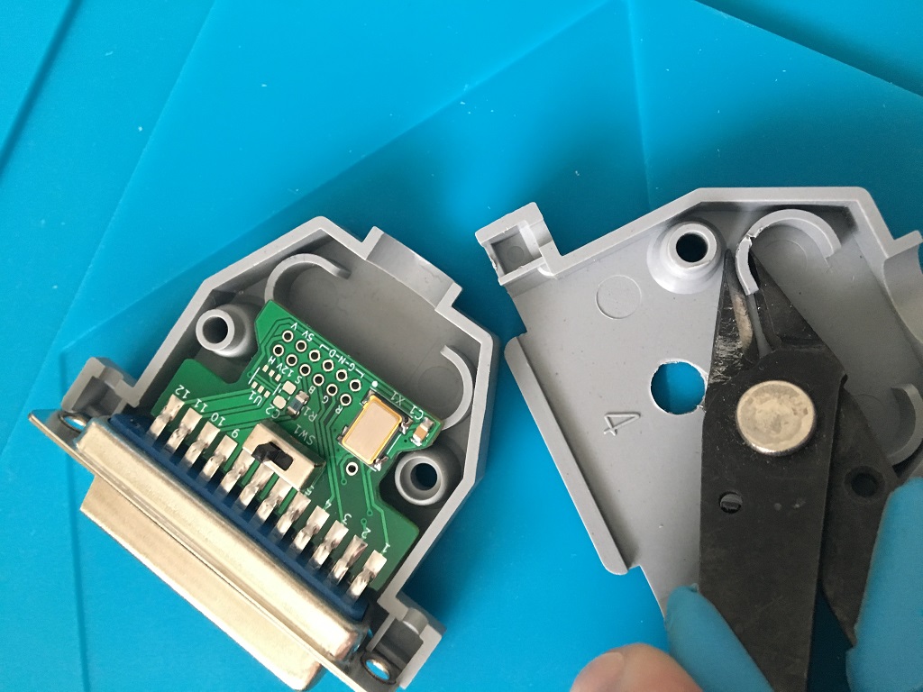
Drill out a hole for the switch 5 mm or similar and if needed cut some plastic from the shroud to clear the oscillator:


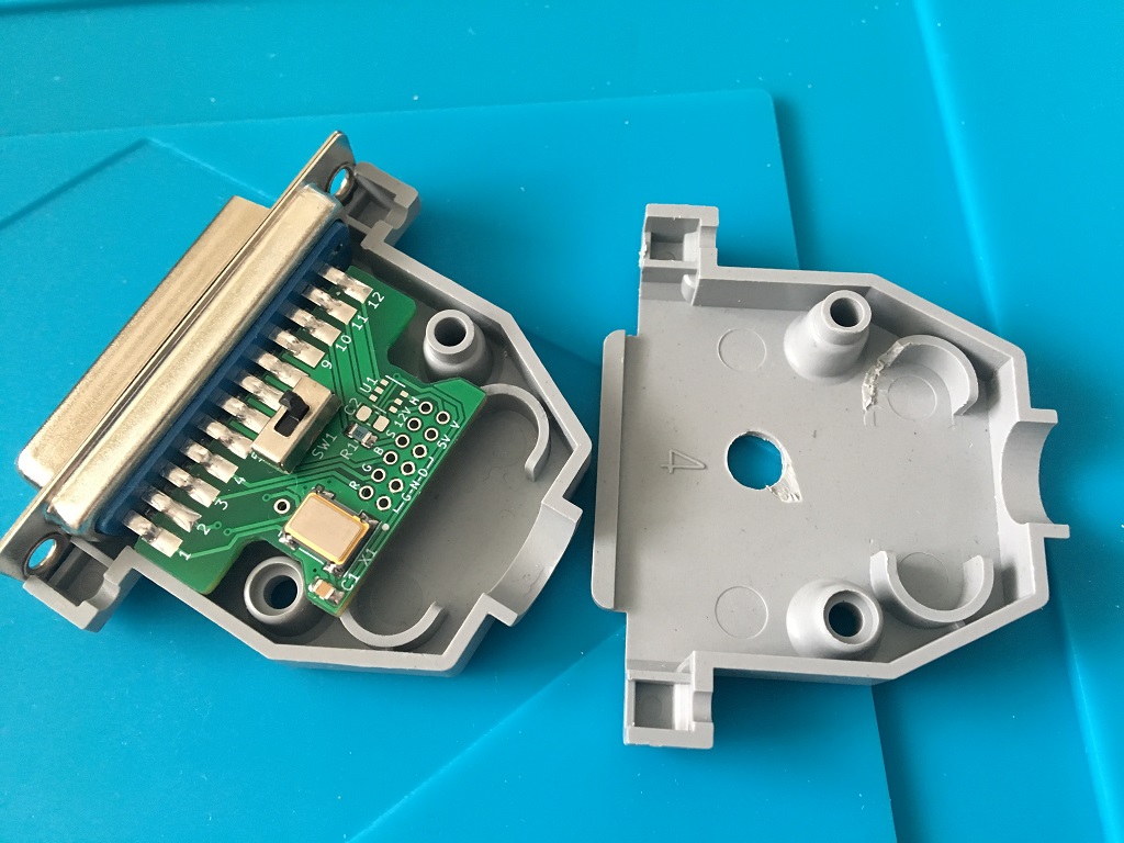
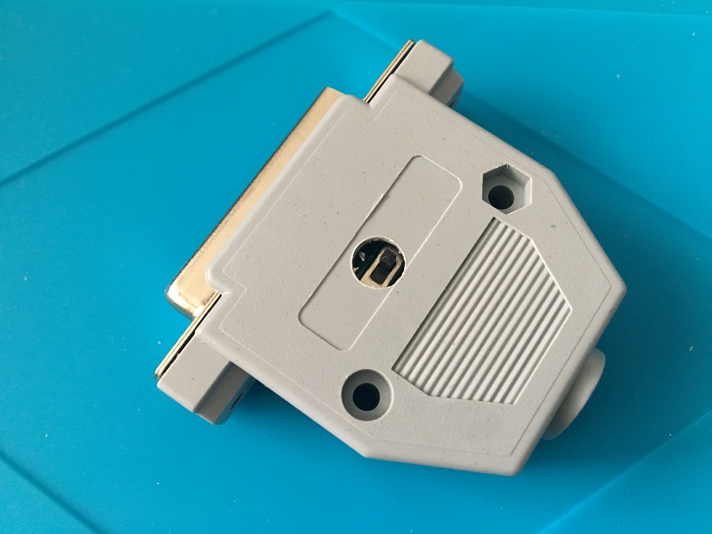
Now, add shrinktubes on the main cable and for the shielding and the L and R audio wires...then solder all the wires to the PCB and crimp the audio wires together, audio GND can be wired together and soldered to the GND pad(s) of the PCB:
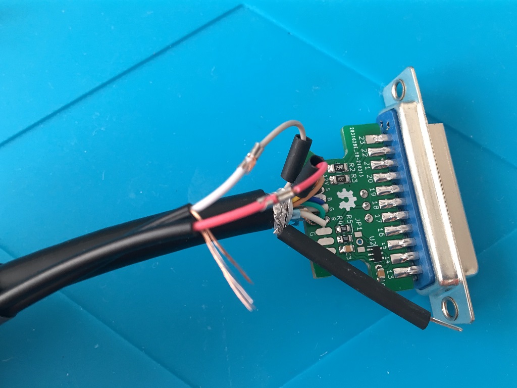
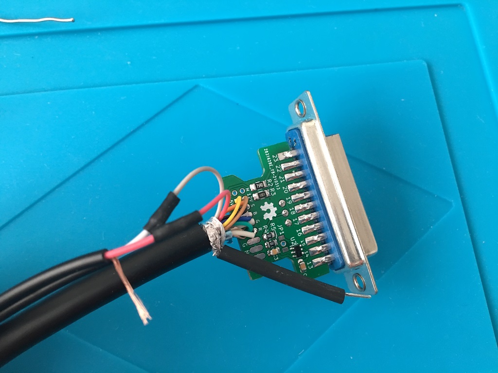
Add the jumper-wire-pin and solder the slide switch and the shielding last (I use my desolder gun 80W to be able to solder the shielding):
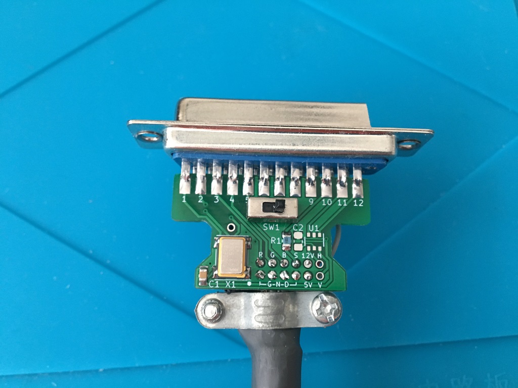
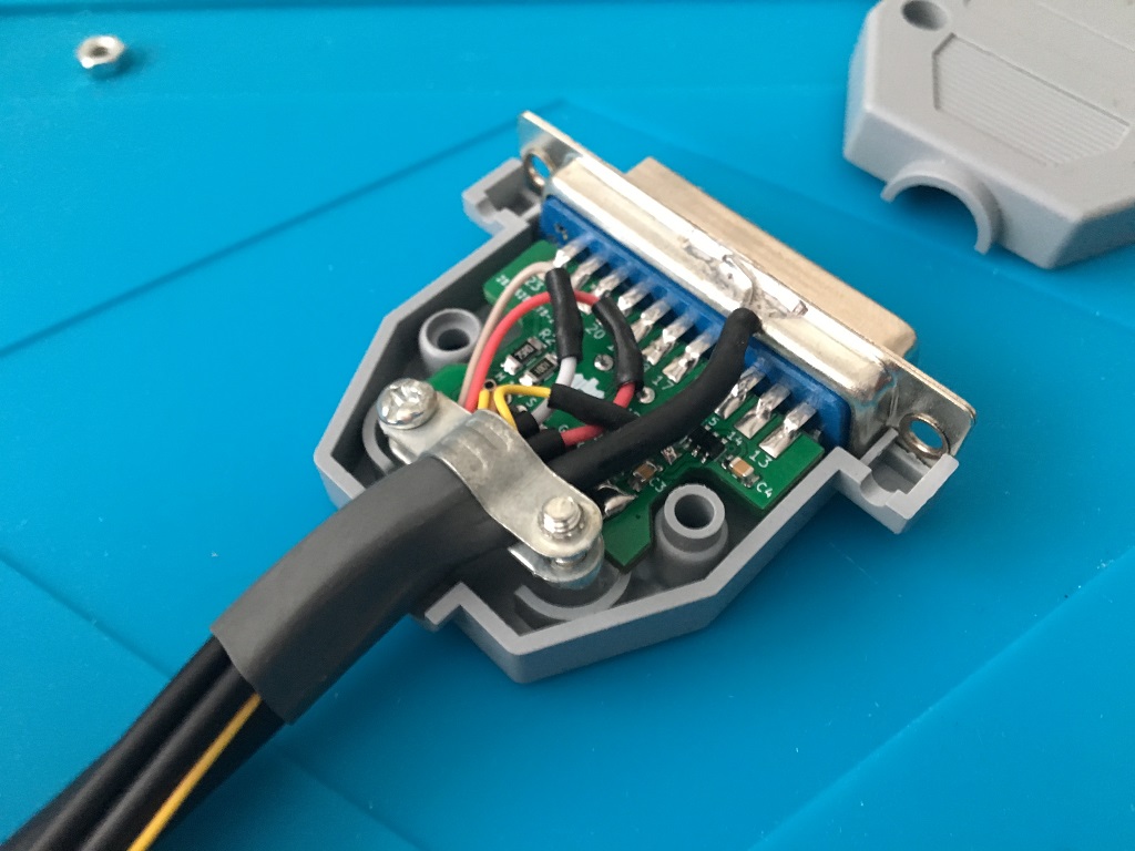
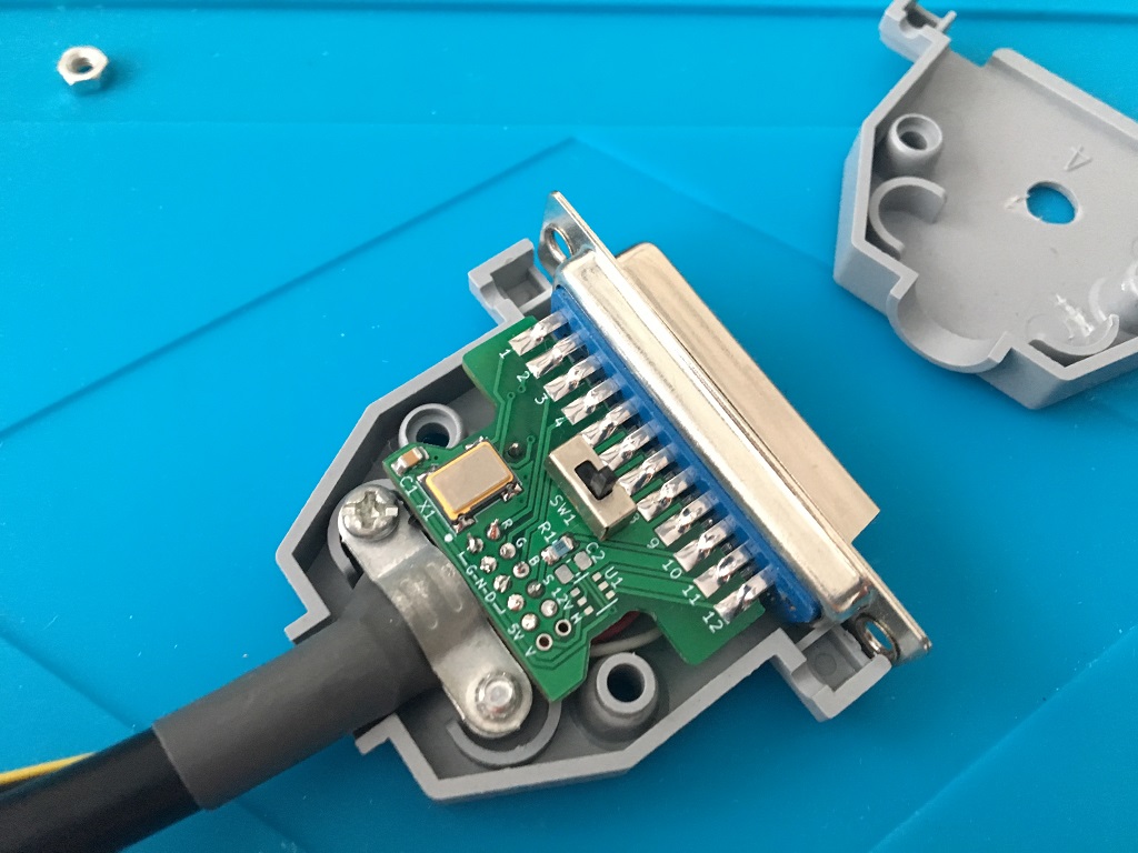
Ok all done with the d-sub connector...
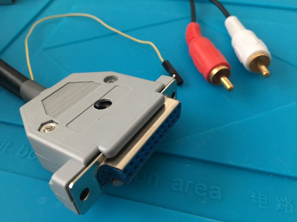
...now the Scart-plug, this is straight forward soldering, nothing special, I use a stick from a q-tip to separate the pin rows to not risk any shorts. I find it holds the pins better in position too.
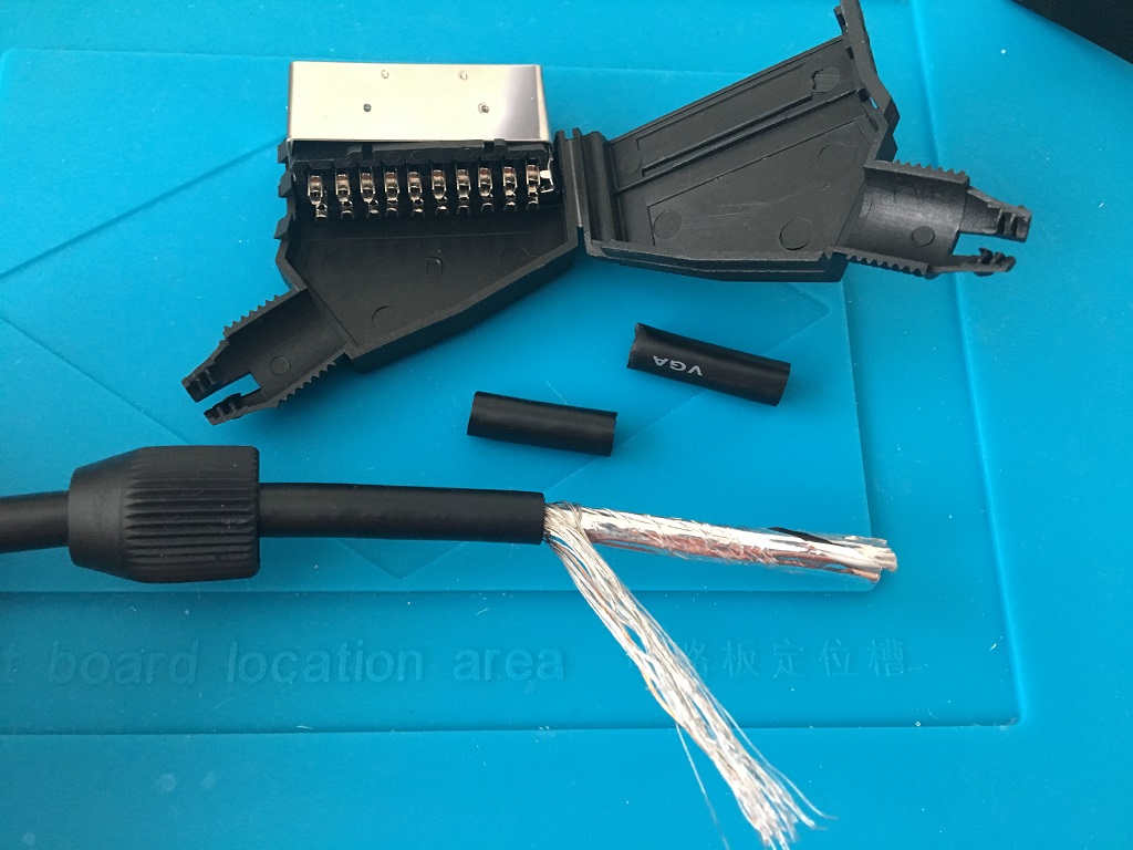
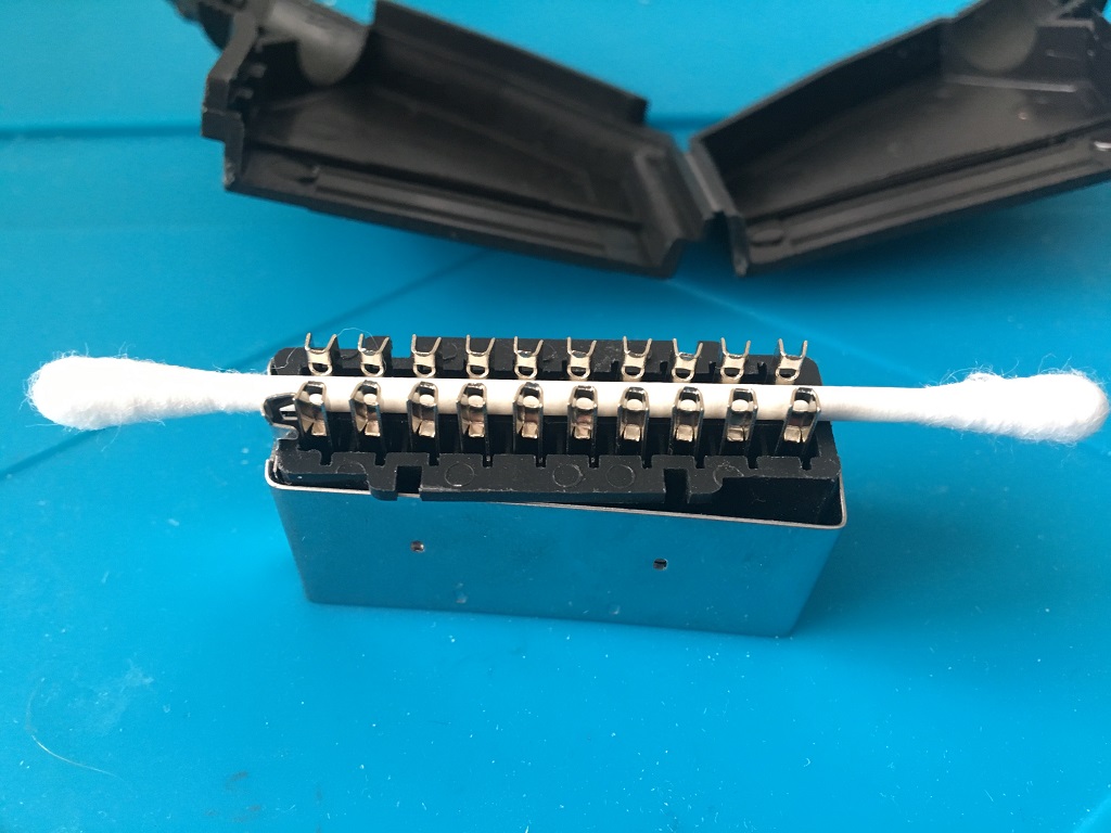
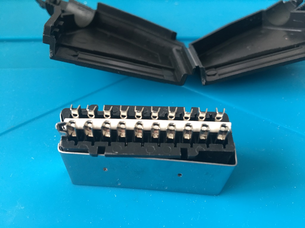
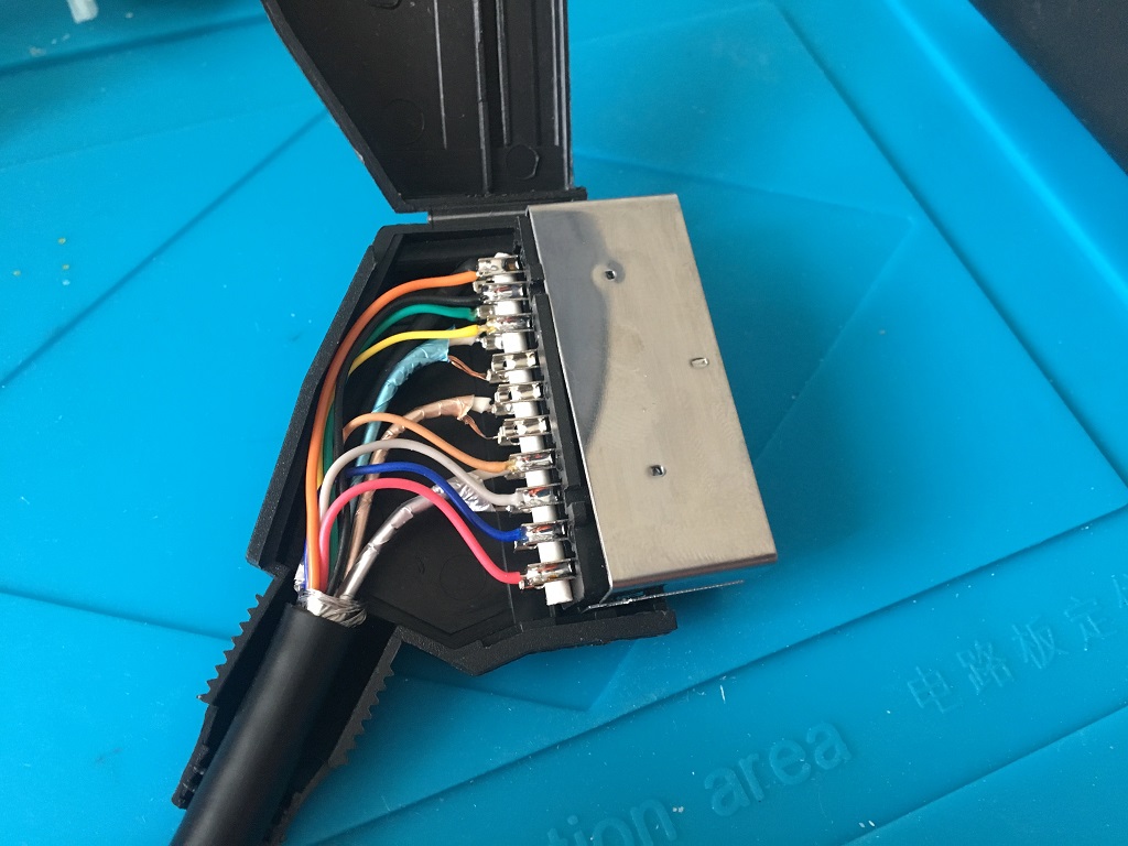
All done!
Here another SCART-cable I made, this time with a real DB23 plug:
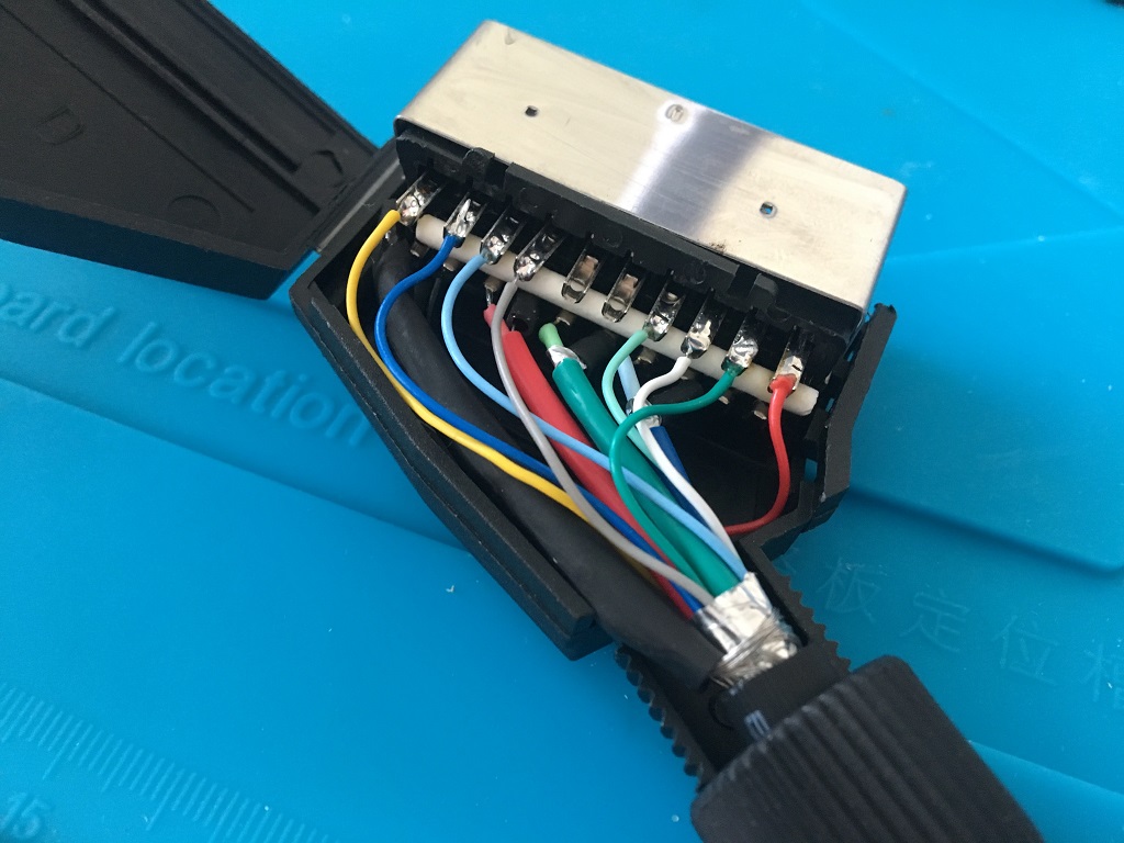
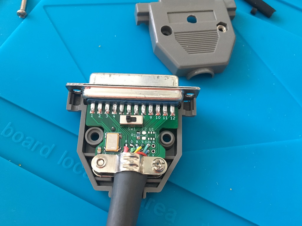
As a last step, don't forget to select Game Mode and the correct AV-mode on your TV.
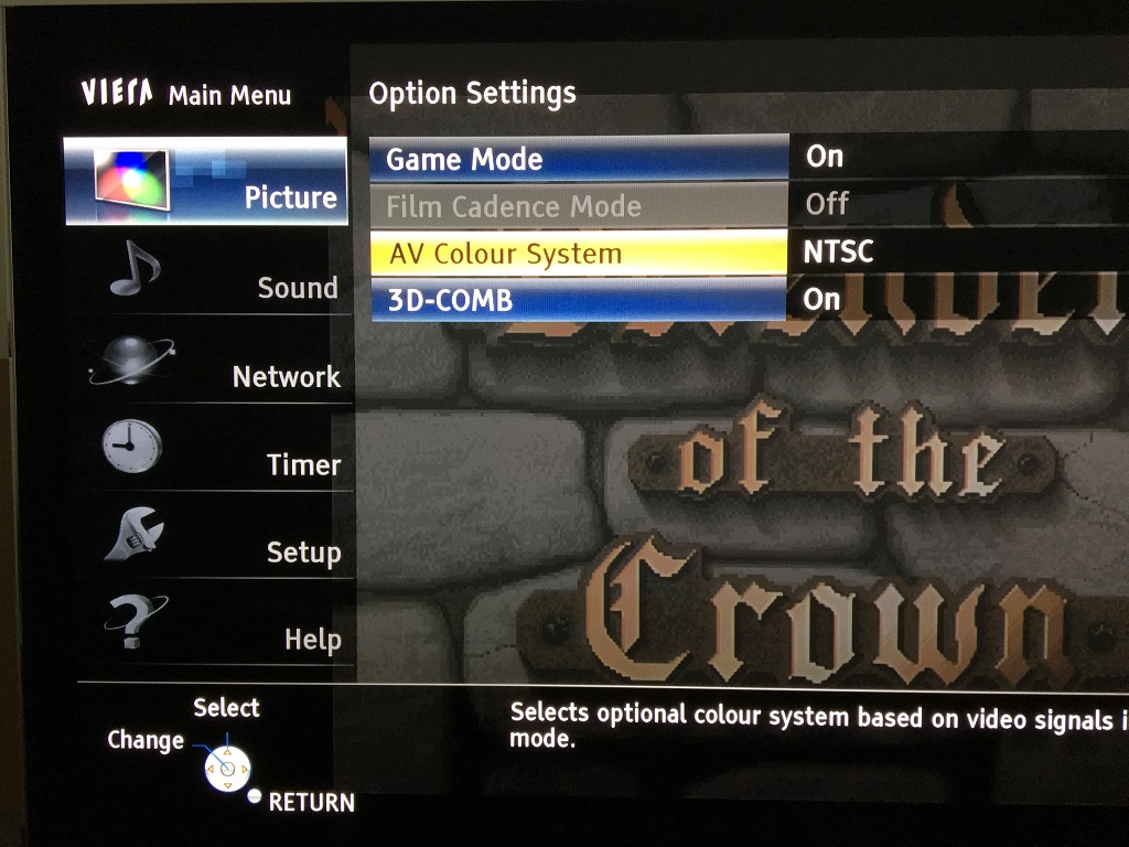
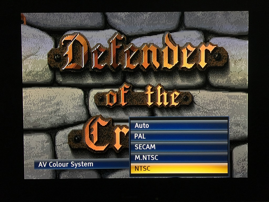
Game On!
Happy Hackin´
This work is licensed under a Creative Commons Attribution-ShareAlike 4.0 International License.

