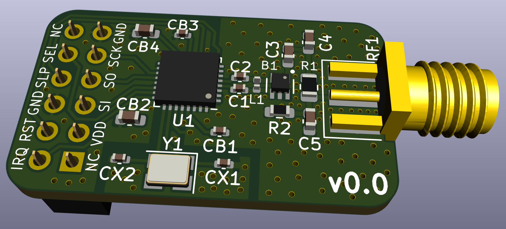
This Repository contains an AT86RF233 breakout board that uses the basic application schematic given in Section 5.1 "Basic Application Schematic" on page 15 of the AT86RF233 datasheet (07/2014), with two differences:
- The optional clock output is omitted
- The 2.4 gigahertz antenna circuit from the AT86RF215-XPRO is used instead the on given in the AT86RF233 basic application schematic. The shielding used in the AT86RF215-XPRO is omitted.
This board is intentionally pin compatible with the openlabs.co RPI 802.15.4 radio - but not based on their design.
- It is highly recommended to not order PCBs based on this design as of now. This design has never been tested.
- There is absolutely no warranty.
- The AT86RF233 chip, the 2 x 6 female pin header, and the SMA connector are note included in the generated BOM an need to be hand soldered.
