Controlling RGB LED display with Raspberry Pi GPIO
A library to control commonly available 64x64, 32x32 or 16x32 RGB LED panels with the Raspberry Pi. Can support PWM up to 11Bit per channel, providing true 24bpp color with CIE1931 profile.
Supports 3 chains with many panels each. On a Raspberry Pi 2 or 3, you can easily chain 12 panels in that chain (so 36 panels total), but you can theoretically stretch that to up to 96-ish panels (32 chain length) and still reach around 100Hz refresh rate with full 24Bit color (theoretical - never tested this; there might likely be timing problems with the panels that will creep up then).
With fewer colors or so-called 'outdoor panels' you can control even more, faster.
The LED-matrix library is (c) Henner Zeller h.zeller@acm.org, licensed with GNU General Public License Version 2.0 (which means, if you use it in a product somewhere, you need to make the source and all your modifications available to the receiver of such product so that they have the freedom to adapt and improve).
Overview
The RGB LED matrix panels can be scored at Sparkfun, AdaFruit or eBay and Aliexpress. If you are in China, I'd try to get them directly from some manufacturer, Taobao or Alibaba.
The RGBMatrix class provided in include/led-matrix.h does what is needed
to control these. You can use this as a library in your own projects or just
use the demo binary provided here which provides some useful examples.
Check out utils/ directory for some ready-made tools to get started using the library, or the examples-api-use/ directory if you want to get started programming your own utils.
All Raspberry Pi versions supported
This supports the old Raspberry Pi's Version 1 with 26 pin header and also the B+ models, the Pi Zero, as well as the Raspberry Pi 2 and 3 with 40 pins. The 26 pin models can drive one chain of RGB panels, the 40 pin models up to three chains in parallel (each chain 12 or more panels long).
The Raspberry Pi 2 and 3 are faster and generally perferred to the older models (and the Pi Zero). With the faster models, the panels sometimes can't keep up with the speed; check out this troubleshooting section what to do.
A lightweight, non-GUI, distribution such as Raspbian Lite or DietPi is recommended.
Types of Displays
There are various types of displays that come all with the same Hub75 connector. They vary in the way the multiplexing is happening.
| Type w*h | Scan Multiplexing | Program commandline flags | Remark |
|---|---|---|---|
| 64x64 | 1:32 | --led-rows=64 --led-cols=64 | For displays with A,B,C,D,E line. |
| 64x64 | 1:32 | --led-rows=64 --led-cols=64 --led-row-addr-type=1 | For displays with A,B lines. |
| 64x32 | 1:16 | --led-rows=32 --led-cols=64 | |
| 64x32 | 1:8 | --led-rows=32 --led-cols=64 --led-multiplexing=1 | few mux choices |
| 32x32 | 1:16 | --led-rows=32 | |
| 32x32 | 1:8 | --led-rows=32 --led-multiplexing=1 | few mux choices |
| 32x16 | 1:8 | --led-rows=16 | |
| 32x16 | 1:4 | --led-rows=16 --led-multiplexing=1 | few mux choices |
| 32x16 | 1:4 | --led-rows=16 --led-row-addr-type=2 --led-multiplexing=4 | For direct A..D address panels. |
| ... |
These can be chained by connecting the output of one panel to the input of the next panel. You can chain quite a few together.
The 64x64 matrixes typically come in two kinds: with 5 address
lines (A, B, C, D, E), or (A, B); the latter needs a --led-row-addr-type=1
parameter. So-called 'outdoor panels' are typically brighter and allow for
faster refresh-rate for the same size, but do some multiplexing internally
of which there are a few types out there; they can be chosen with
the --led-multiplexing parameter.
Generally, the higher scan-rate (e.g. 1:8), a.k.a. outdoor panels generally allow faster refresh rate, but you might need to figure out the multiplexing mapping if one of the three provided does not work.
Some 32x16 outdoor matrixes with 1:4 scan (e.g. Qiangli Q10(1/4) or X10(1/4))
have 4 address line (A, B, C, D). For such matrices is necessary to
use --led-row-addr-type=2 parameter. Also the matrix Qiangli Q10(1/4)
have "Z"-stripe pixel mapping and in this case, you'd use two parameters
at the same time --led-row-addr-type=2 --led-multiplexing=4.
Let's do it
This documentation is split into parts that help you through the process
 Wire up the matrix to your Pi. This document describes
what goes where. You might also be interested
in breakout boards for that.
If you have an Adafruit HAT or Adafruit Bonnet, you can choose that with
a command line option described below
Wire up the matrix to your Pi. This document describes
what goes where. You might also be interested
in breakout boards for that.
If you have an Adafruit HAT or Adafruit Bonnet, you can choose that with
a command line option described below- Run a demo. You find that in the examples-api-use/ directory:
make -C examples-api-use
sudo examples-api-use/demo -D0
- Use the utilities. The utils directory has some ready-made useful utilities to show content. Go there to see how to compile and run these.
- Write your own programs using the Matrix in C++ or Python.
Utilities
The utils directory is meant for ready utilities to show images or animated gifs or videos. Read the README there for instructions how to compile.
There are external projects that use this library and provide higher level network protocols, such as the FlaschenTaschen implementation (VLC can send videos to it natively) or the PixelPusher implementation (common in light art installations).
API
The library comes as an API that you can use for your own utilities and use-cases.
- The native library is a C++ library (see include/). Example uses you find in the examples-api-use/ directory.
- If you prefer to program in C, there is also a C API.
- In the python subdirectory, you find a Python API including a couple of examples to get started.
- There are a couple of external bindings, such as
- Nodejs binding by Maxime Journaux.
- Go binding by Máximo Cuadros
- Rust binding by Vincent Pasquier
Changing parameters via command-line flags
For the programs in this distribution and also automatically in your own programs using this library, there are a lot of parameters provided as command line flags, so that you don't have to re-compile your programs to tweak them. Some might need to be changed for your particular kind of panel.
Here is a little run-down of what these command-line flags do and when you'd like to change them.
First things first: if you have a different wiring than described in wiring, for instance if you have an Adafruit HAT/Bonnet, you can choose these here:
--led-gpio-mapping=<gpio-mapping>: Name of GPIO mapping used. Default "regular"
This can have values such as
--led-gpio-mapping=regularThe standard mapping of this library, described in the wiring page.--led-gpio-mapping=adafruit-hatThe Adafruit HAT/Bonnet, that uses this library or--led-gpio-mapping=adafruit-hat-pwmAdafruit HAT with the anti-flicker hardware mod described below.
The next most important flags describe the type and number of displays connected
--led-rows=<rows>        : Panel rows. Typically 8, 16, 32 or 64. (Default: 32).
--led-cols=<cols>        : Panel columns. Typically 32 or 64. (Default: 32).
--led-chain=<chained>    : Number of daisy-chained panels. (Default: 1).
--led-parallel=<parallel>: For A/B+ models or RPi2,3b: parallel chains. range=1..3 (Default: 1).
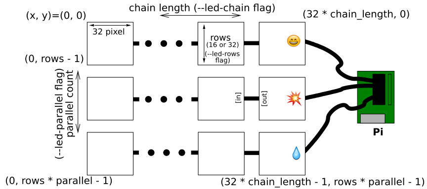
These are the most important ones: here you choose how many panels you have
connected and how many rows are in each panel. Panels can be chained (each panel
has an input and output connector, see the
wiring documentation) -- the --led-chain flag tells the
library how many panels are chained together. The newer Raspberry Pi's allow
to connect multiple chains in parallel, the --led-parallel flag tells it how
many there are.
This illustrates what each of these parameters mean:
Multiplexing
If you have some 'outdoor' panels or panels with different multiplexing, the following will be useful:
--led-multiplexing=<0..4> : Multiplexing type: 0=direct; 1=strip; 2=checker; 3=spiral; 4=Z-strip (Default: 0)
The outdoor panels have different multiplexing which allows them to be faster and brighter, but by default their output looks jumbled up. They require some pixel-mapping of which there are a few types you can try and hopefully one of them works for your panel; The default=0 is no mapping ('standard' panels), while 1, 2, 3 or 4 are different mappings to try with. If your panel has a different mapping, please send a pull request.
Note that you have to set the --led-rows and --led-cols to the rows and
columns that are physically on each chained panel so that the multiplexing
option can work properly. For instance a 32x16 panel with 1:4 multiplexing
would be controlled with --led-rows=16 --led-cols=32 --led-multiplexing=1 (or
whatever multiplexing type your panel is, so it can also be --led-multiplexing=2, or 3).
For 64x32 panels with 1:8 multiplexing, this would typically be
--led-rows=32 --led-cols=64 --led-multiplexing=1;
however, there are some panels that internally behave like
two chained panels, so then you'd use
--led-rows=32 --led-cols=32 --led-chain=2 --led-multiplexing=1;
--led-pixel-mapper : Semicolon-separated list of pixel-mappers.
Mapping the logical layout of your boards to your physical arrangement. See more in Remapping coordinates.
--led-row-addr-type=<0..2>: 0 = default; 1=AB-addressed panels; 2=direct row select (Default: 0).
This option is useful for certain 64x64 or 32x16 panels. For 64x64 panels,
that only have an A and B address line, you'd use --led-row-addr-type=1.
This is only tested with one panel so far, so if it doesn't work for you,
please send a pull request.
For 32x16 outdoor panels, that have have 4 address line (A, B, C, D), it is
necessary to use --led-row-addr-type=2.
--led-brightness=<percent>: Brightness in percent (Default: 100).
Self explanatory.
--led-pwm-bits=<1..11> : PWM bits (Default: 11).
The LEDs can only be switched on or off, so the shaded brightness perception is achieved via PWM (Pulse Width Modulation). In order to get a good 8 Bit per color resolution (24Bit RGB), the 11 bits default per color are good (why ? Because our eyes are actually perceiving brightness logarithmically, so we need a lot more physical resolution to get 24Bit sRGB).
With this flag, you can change how many bits it should use for this; lowering it means the lower bits (=more subtle color nuances) are omitted. Typically you might be mostly interested in the extremes: 1 Bit for situations that only require 8 colors (e.g. for high contrast text displays) or 11 Bit for everything else (e.g. showing images or videos). Why would you bother at all ? Lower number of bits use slightly less CPU and result in a higher refresh rate.
--led-show-refresh : Show refresh rate.
This shows the current refresh rate of the LED panel, the time to refresh a full picture. Typically, you want this number to be pretty high, because the human eye is pretty sensitive to flicker. Depending on the settings, the refresh rate with this library are typically in the hundreds of Hertz but can drop low with very long chains. Humans have different levels of perceiving flicker - some are fine with 100Hz refresh, others need 250Hz. So if you are curious, this gives you the number (shown on the terminal).
The refresh rate depends on a lot of factors, from --led-rows and --led-chain
to --led-pwm-bits, --led-pwm-lsb-nanoseconds and --led-pwm-dither-bits.
If you are tweaking these parameters, showing the refresh rate can be a
useful tool.
--led-scan-mode=<0..1> : 0 = progressive; 1 = interlaced (Default: 0).
This switches from progressive scan and interlaced scan. The latter might look be a little nicer when you have a very low refresh rate, but typically it is more annoying because of the comb-effect (remember 80ies TV ?).
--led-pwm-lsb-nanoseconds : PWM Nanoseconds for LSB (Default: 130)
This allows to change the base time-unit for the on-time in the lowest significant bit in nanoseconds. Lower values will allow higher frame-rate, but will also negatively impact qualty in some panels (less accurate color or more ghosting).
Good values for full-color display (PWM=11) are somewhere between 100 and 300.
If you you use reduced bit color (e.g. PWM=1) and have sharp contrast applications, then higher values might be good to minimize ghosting.
How to decide ? Just leave the default if things are fine. But some panels have trouble with sharp contrasts and short pulses that results in ghosting. It is particularly apparent in situations such as bright text on black background. In these cases increase the value until you don't see this ghosting anymore.
The following example shows how this might look like:
| Ghosting with low --led-pwm-lsb-nanoseconds | No ghosting after tweaking |
|---|---|
 |
 |
If you tweak this value, watch the framerate (--led-show-refresh) while playing
with this number.
--led-pwm-dither-bits : Time dithering of lower bits (Default: 0)
The lower bits can be time dithered, i.e. their brightness contribution is
achieved by only showing them some frames (this is possible,
because the PWM is implemented as binary code modulation).
This will allow higher refresh rate (or same refresh rate with increased
--led-pwm-lsb-nanoseconds).
The disadvantage could be slightly lower brightness, in particular for longer
chains, and higher CPU use.
CPU use is not of concern for Rasbperry Pi 2 or 3 (as we run on a dedicated
core anyway) but proably for Raspberry Pi 1 or Pi Zero.
Default: no dithering; if you have a Pi 3 and struggle with low frame-rate due
to high multiplexing panels (1:16 or 1:32) or long chains, it might be
worthwhile to try.
--led-slowdown-gpio=<0..2>: Slowdown GPIO. Needed for faster Pis and/or slower panels (Default: 1).
The Raspberry Pi 2 and 3 are putting out data too fast for almost all LED panels I have seen. In this case, you want to slow down writing to GPIO. Zero for this parameter means 'no slowdown'.
The default 1 (one) typically works fine, but often you have to even go further by setting it to 2 (two). If you have a Raspberry Pi with a slower processor (Model A, A+, B+, Zero), then a value of 0 (zero) might work and is desirable.
--led-no-hardware-pulse : Don't use hardware pin-pulse generation.
This library uses a hardware subsystem that also is used by the sound. You can't use them together. If your panel does not work, this might be a good start to debug if it has something to do with the sound subsystem (see Troubleshooting section). This is really only recommended for debugging; typically you actually want the hardware pulses as it results in a much more stable picture.
--led-no-drop-privs : Don't drop privileges from 'root' after initializing the hardware.
You need to start programs as root as it needs to access some low-level hardware at initialization time. After that, it is typically not desirable to stay in this role, so the library then drops the privileges.
This flag allows to switch off this behavior, so that you stay root. Not recommended unless you have a specific reason for it.
--led-daemon : Make the process run in the background as daemon.
If this is set, the program puts itself into the background (running as 'daemon'). You might want this if started from an init script at boot-time.
--led-inverse             : Switch if your matrix has inverse colors on.
--led-rgb-sequence        : Switch if your matrix has led colors swapped (Default: "RGB")
These are if you have a different kind of LED panel in which the logic of the
color bits is reversed (--led-inverse) or where the Red, Green and Blue LEDs
are mixed up (--led-rgb-sequence). You know it when you see it.
Troubleshooting
Here are some tips in case things don't work as expected.
Use minimal Raspbian distribution
In general, run a minimal configuration on your Pi.
-
Do not use a graphical user interface (Even though the Raspberry Pi foundation makes you believe that you can do that: don't. Using a Pi with a GUI is a frustratingly slow use of an otherwise perfectly good embedded device.)
-
Switch off on-board sound (
dtparam=audio=offin/boot/config.txt). External USB sound adapters work, and are much better quality anyway, so that is recommended if you happen to need sound. The on-board sound uses a timing circuit that the RGB-Matrix needs (it seems in some distributions, such as arch-linux, this is not enough and you need to explicitly blacklist the snd_bcm2835 module). -
Don't run anything that messes in parallel with the GPIO pins, e.g. PiGPIO library/daemon or devices that use the i2c or 1-wire interface if they are on the same pins you need for the panel.
-
I have also seen reports that on some Pis, the one-wire protocol is enabled (w1-gpio). This will also not work (disable by removing
dtoverlay=w1-gpioin/boot/config.txt; or usingraspi-config, Interface Options -> 1-Wire) -
If you see some regular flickering, make sure that there is no other process running on the system that could cause that. For instance, it is known that merely running
topcreates a faint flicker every second it updates. Or a regular ntp run can also cause flicker once a minute (switch off withsudo timedatectl set-ntp false). Maybe instead you might want to run ntp at system start-up but then not regularly updating. There might be other things running regularly you don't need; consider asudo systemctl stop cronfor instance. -
There are probably other processes that are running that you don't need and remove them; I usually remove right away stuff I really don't need e.g.
sudo apt-get remove bluez bluez-firmware pi-bluetooth triggerhappy pigpioTake a close look at your systemd (
systemctl) and see if there are other things running you don't need. If you have seen packages in standard Raspbians that interfere with the matrix code, let me know to include it here. In general: This is why starting with a minimal installation is a good idea: there is simply less cruft that you have to disable. -
It seems that more recent version of Raspbian Lite result in some faint brightness fluctuations of the displays and it is not quite clear why (see issue #483). If you are a Kernel person and can help figuring out what is happening that would be very appreciated. Also, you might know a minimal Linux distribution that is more suited for near realtime applications ?
The default install of Raspbian Lite or DietPi seem to be good starting points, as they have a reasonably minimal configuration to begin with.
Bad interaction with Sound
If sound is enabled on your Pi, this will not work together with the LED matrix,
as both need the same internal hardware sub-system (a first test to see if you
are affected is to run the progrem with --led-no-hardware-pulse and see if
things work fine then).
If you run lsmod and see the snd_bcm2835 module, this could be causing trouble.
(The library actually exits if it finds this module to be loaded).
In that case, you should create a kernel module blacklist file like the following on your system and update your initramfs:
cat <<EOF | sudo tee /etc/modprobe.d/blacklist-rgb-matrix.conf
blacklist snd_bcm2835
EOF

sudo update-initramfs -u
Reboot and confirm that the module is not loaded.
I have followed some tutorial on the Internet and it doesn't work
Well, if you use this library, please read the documentation provided here, not on some other website. Most important for you to get started is the wiring guide. There are some tutorials floating around that refer to a very old version of this library.
I have a Pi1 Revision1 and top part of Panel doesn't show green
Use --led-gpio-mapping=regular-pi1
Logic level voltage not sufficient
Some panels don't interpret the 3.3V logic level well, or the RPi output drivers have trouble driving longer cables, in particular with faster Raspberry Pis Version 2. This results in artifacts like randomly showing up pixels, color fringes, or parts of the panel showing 'static'.
If you encounter this, try these things
-
Make sure to have as short as possible flat-cables connecting your Raspberry Pi with the LED panel.
-
In particular if the chips close to the input of the LED panel read 74HC245 instead of 74HCT245 or 74AHCT245, then this board will not work properly with 3.3V inputs coming from the Pi. Use an adapter board with a bus-driver that acts as level shifter between 3.3V and 5V. (In any case, it is always a good idea to use the level shifters).
-
A temporary hack to make HC245 inputs work with the 3.3V levels is to supply only like 4V to the LED panel. But the colors will be off, so not really useable as long-term solution.
-
If you can't implement the above things, or still have problems, you can slow down the GPIO writing a bit. This will of course reduce the frame-rate, so it comes at a cost.
For GPIO slow-down, add the flag --led-slowdown-gpio=2 to the invocation of
the binary.
If you have an Adafruit HAT or Bonnet
Generally, if you want to connect RGB panels via an adapter instead of hand-wiring, I suggest to build one of the adapters whose open-hardware files you find in the adapter/ subdirectory. It is a fun solder exercise with large surface mount components.
However, Adafruit offers an adapter which is already ready-made, but it only allows for a single chain. If the ready-made vs. single-chain tradeoff is worthwhile, then you might go for that (I am not affiliated with Adafruit).
Switch the Pinout
The Adafruit HAT/Bonnet uses this library but a modified pinout to support other features on the HAT. You can choose the Adafruit pinout with a command line flag.
Just pass the option --led-gpio-mapping=adafruit-hat. This works on the C++
and Python examples.
If you want to have this a compiled-in default, add the following setting in front of your compilation:
HARDWARE_DESC=adafruit-hat make
(alternatively, you can modify the lib/Makefile and change it there directly)
Then re-compile and the new flag default is now adafruit-hat, so
no need to set it on the command line.
Improving flicker
To improve flicker, we need to do a little hardware modification, but it is very simple: solder a wire between GPIO 4 and 18 as shown in the following picture (click to enlarge):

Then, start your programs with --led-gpio-mapping=adafruit-hat-pwm.
If you want to make this the default setting your program starts with, you can also manually choose this with
HARDWARE_DESC=adafruit-hat-pwm make
to get this as default setting.
Now you should have less visible flicker. This essentially switches on the hardware pulses feature for the Adafruit HAT/Bonnet.
64x64 with E-line on Adafruit HAT/Bonnet
There are LED panels that have 64x64 LEDs packed, but they need 5 address lines,
which is 1:32 multiplexing (they have an E address-line). The hardware of
the Adafruit HAT/Bonnet is not prepared for this, but it can be done with another
hardware mod.
It is a little more advanced hack, so is only really for people who are comfortable with this kind of thing. First, you have to figure out which is the input of the E-Line on your matrix (they seem to be either on Pin 4 or Pin 8 of the IDC connector). You need to disconnect that Pin from the ground plane (e.g. with an Exacto knife) and connect GPIO 24 to it. The following images illustrate the case for IDC Pin 4.


If the direct connection does not work, you need to send it through a free level converter of the Adafruit HAT/Bonnet. Since all unused inputs are grounded with traces under the chip, this involves lifting a leg from the HCT245 (figure out a free bus driver from the schematic). If all of the above makes sense to you, you have the Ninja level to do it!
It might be more convienent at this point to consider the Active3 adapter that has that covered already.
Running as root
The library requires to access hardware registers to control the LED matrix, and create accurate timings. These hardware accesses require to run as root user.
For security reasons, it is usually not a good idea to run an application as root entirely, so this library makes sure to drop privileges immediately after the hardware is initialized.
You can switch off the privilege dropping with the
--led-no-drop-privs flag, or, if you do this
programmatically,
choose the configuration in the
RuntimeOptions struct.
Note, you could run as non-root, which will use /dev/gpiomem
to at least write to GPIO, however the precise timing hardware registers are
not accessible. This will result in flicker and color degradation. Starting
as non-root is not recommended.
CPU use
These displays need to be updated constantly to show an image with PWMed LEDs. This is dependent on the length of the chain: for each chain element, about 1'000'000 write operations have to happen every second! (chain_length * 32 pixel long * 16 rows * 11 bit planes * 180 Hz refresh rate).
We can't use hardware support for writing these as DMA is too slow, thus the constant CPU use on an RPi is roughly 30-40% of one core. Keep that in mind if you plan to run other things on this computer (This is less noticable on Raspberry Pi, Version 2 or 3 that has more cores).
Also, the output quality is susceptible to other heavy tasks running on that computer - there might be changes in the overall brigthness when this affects the referesh rate.
If you have a loaded system and one of the newer Pis with 4 cores, you can reserve one core just for the refresh of the display:
isolcpus=3
.. at the end of the line of /boot/cmdline.txt (needs to be in the same as
the other arguments, no newline). This will use the last core
only to refresh the display then, but it also means, that no other process can
utilize it then. Still, I'd typically recommend it.
Limitations
If you are using the Adafruit HAT/Bonnet in the default configuration, then we can't make use of the PWM hardware (which only outputs to a particular pin), so you'll see random brightness glitches. I strongly suggest to do the aforementioned hardware mod.
The system needs constant CPU to update the display. Using the DMA controller was considered but after extensive experiments ( https://github.com/hzeller/rpi-gpio-dma-demo ) dropped due to its slow speed..
There is an upper limit in how fast the GPIO pins can be controlled, which limits the frame-rate. Raspberry Pi 2's and newer are generally faster.
Even with everything in place, you might see faint brightness fluctuations in particular if there is something going on on the network or in a terminal on the Pi; this could probably be mitigated with some more real-time kernel for the Pi; maybe there are also hardware limitations (memory bus contention?). Anyway, if you have a realtime kernel configuration that you have optimized for this application, let me know.
To address the brightness fluctuations, you might experiment with the
FIXED_FRAME_MICROSECONDS compile time option in lib/Makefile
that has instructions how to set it up.
Fun
I am always happy to see users successfully using the software for wonderful things, like this installation by Dirk in Scharbeutz, Germany:
