In this repository you'll find the schematic and PCB layout for the Famicom powerboard replacement as shown in this episode of Hakk's Lab. You'll need Design Spark PCB to open the project files. Exported gerber files can be found in the gerber/ directory.
Below are the parts used in this layout with suggestions for potential improvements or changes.
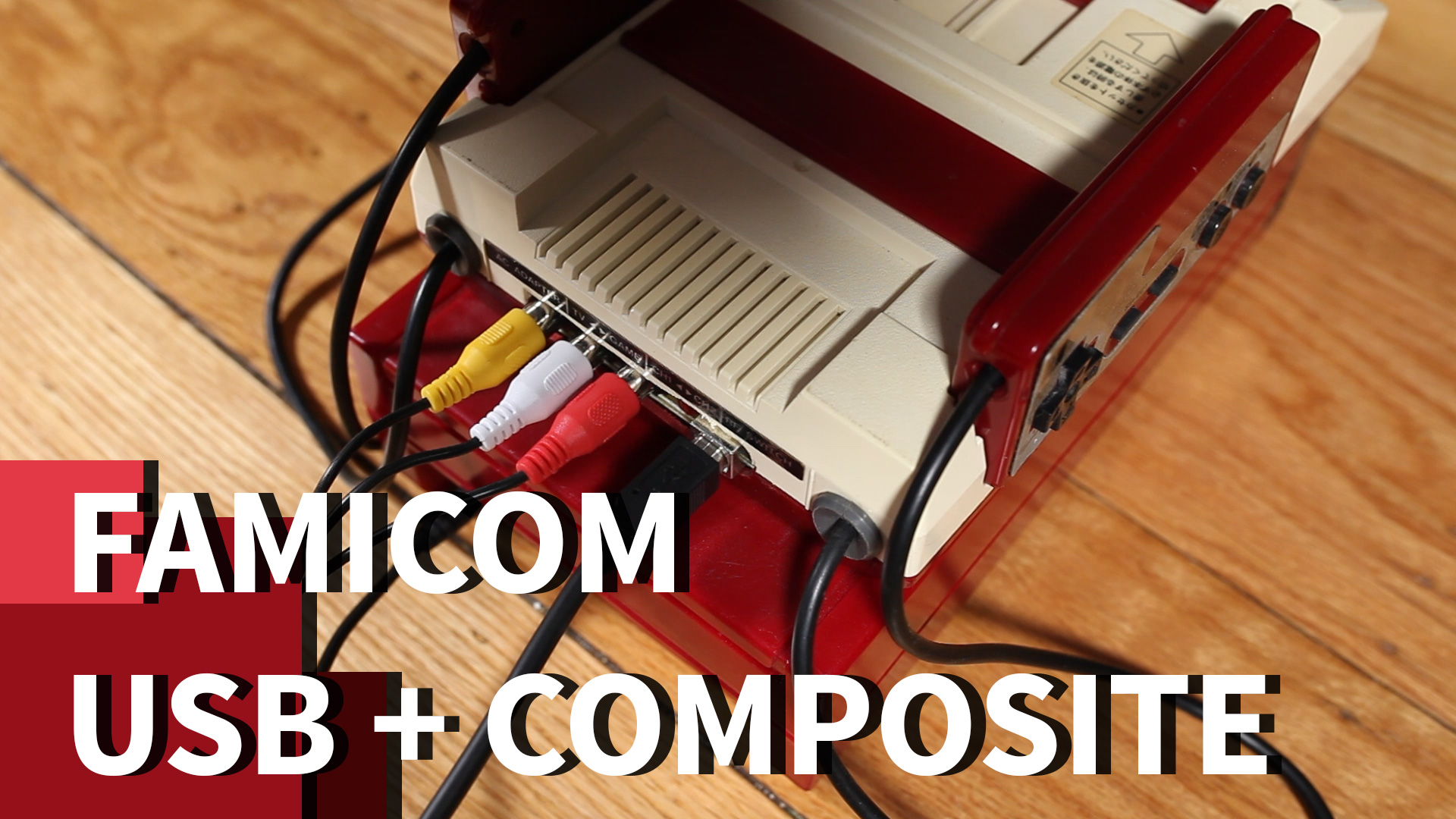
- 1 3 RCA female AV cocentric socket
- 1 USB connector of your choice. For this layout, I used a female USB type-B connector
- 3 150 ohm resistor. Alternatively, two of these could be replaced with a 300 ohm resistor. I didn't have any 300s, so I seriesed up a couple 150s to get the correct resistance
- 1 110 ohm resistor
- 1 PNP transistor
- 1 1uF electrolytic capacitor
- 1 220uF electrolytic capacitor
- 1 red LED. Honestly, it could be any color, but be sure you use the correct resistor for whatever you actually use. I think red is appropriate in this case because 80s technology and it matches the colors of the Famicom.