Front panel binding post modification for HP 6060B/6063B DC electronic load
Any modification of these devices is done at your own risk.
The 6060B and 6063B DC electronic loads are designed to sink a very large amount of power - 300W and 250W respectively. Any modifications to these units can produce very dangerous results if care is not taken to make sure that all additional or replaced parts meet or exceed the design requirements for the unit. When selecting all parts, even seemingly simple parts such as wire, be sure to verify that the new parts can safely carry voltages and current well beyond the ratings of the electronic load itself. Always do your own research and, if necessary, consult experts to assure that the parts you select and actions you undertake are safe.
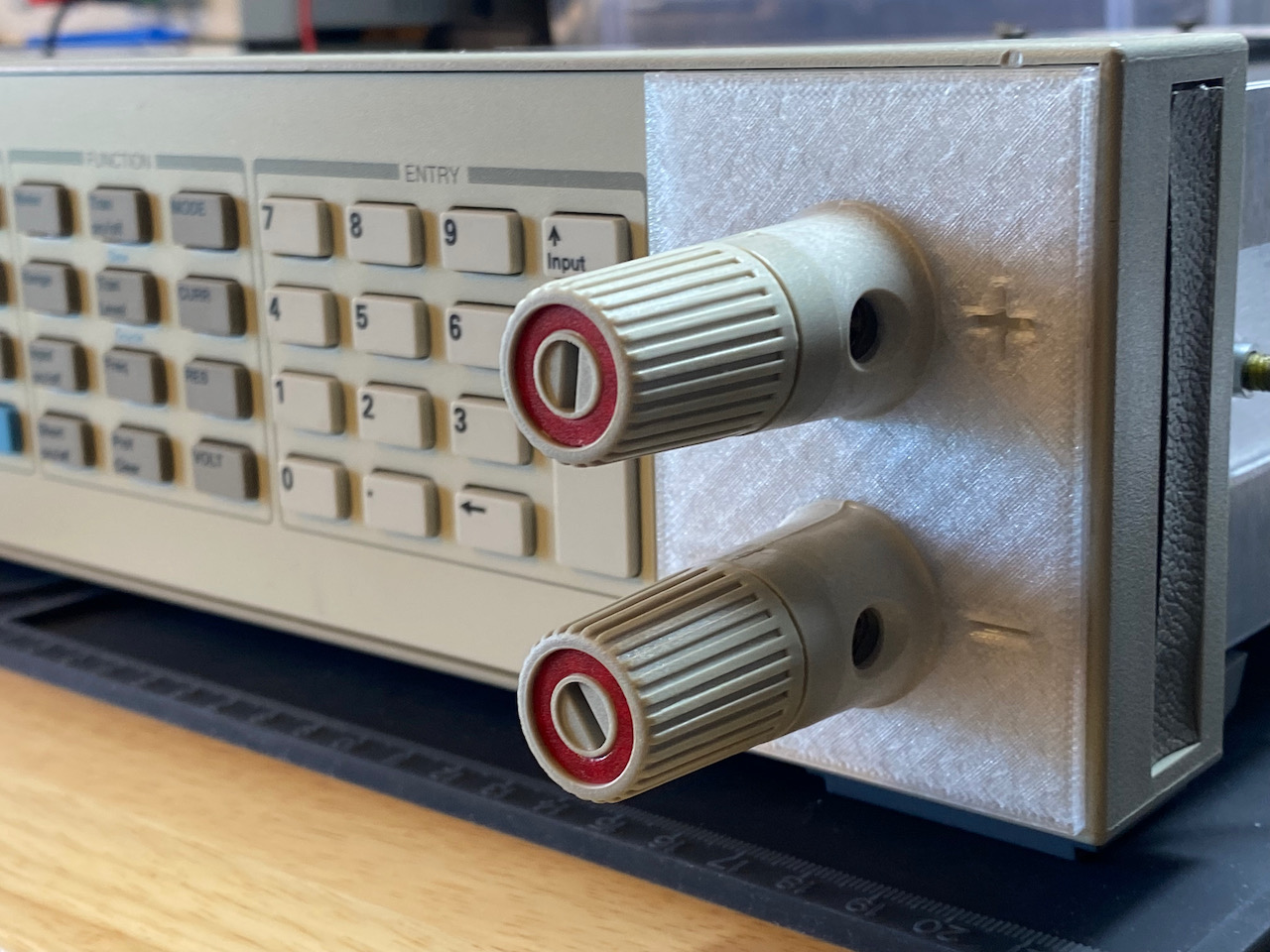
This project consists of an OpenSCAD script to create a 3D printable or CNC machinable panel to aid in mounting front panel binding posts on a Hewlett Packard/Agilent/Keysight 6060B or 6063B DC electronic load.
The HP 6060B/6063B DC electronic load is a wonderful device for testing power supplies but for bench use the lack of front panel inputs can be a bit of a drag. This project aims to fix that by providing a 3D model for a mounting panel and documenting the process of installing front panel binding posts.
A relatively small number of 606xB devices have Option 020 installed. This option adds a second set of binding posts to the front of the device using a modified front panel and some additional parts. Thankfully, HP left behind some mounting holes in the panel's plastic for us to work with which will provide any intrepid maker with a solid starting point for modifying their own non-Option 020 device to include a secondary set of easily accessible binding posts. The HP service manual also includes a lot of detail on the parts used by Option 020, providing the insight required to find parts that can meet or exceed the original specs.
Several other parts will be required in addition to the printed or machined mounting plate. Only the binding posts themselves are single-source and somewhat difficult to find.
- 2x Binding Post, HP P/N
1510-0134- These are unique parts only used in Keysight's electronic loads so they may be hard to find.
- Keysight sells these through their difficult-to-access parts system but can occasionally be found from various third party parts and surplus suppliers. I was lucky enough to spot a pair on 4gte.com while they were available.
- 2x Hex Nut, M12x1.75, 6mm Height, HP P/N
0535-0020- I used this part from McMaster Carr.
- As of mid-2021 I still have a bunch of spares, so send me an email if you're having a hard time finding them
- 2x Washer, Curved, 13mm ID, 0.2mm Thick, Spring Steel, HP P/N
3050-1320- I ended up using two washers from this kit purchased from Amazon US. These washers were definitely not of the same grade as the factory washers on the rear panel
but they appear to be doing their job just fine with a bit of extra tightening. edit: These didn't work out very well and I'd recommend more robust washers for this use. - The Amazon-purchased washers weren't up to par and "went flat" very quickly so I ordered this part from McMaster Carr which appears to be almost identical to the thick, proper spring steel factory originals. After several weeks they're still doing their job, providing the consistent, springy pressure required to hold the posts and mounting plate in place.
- I ended up using two washers from this kit purchased from Amazon US. These washers were definitely not of the same grade as the factory washers on the rear panel
- 2x Machine Screw, M5x0.8, 12mm Length, Pan Head, HP P/N
0515-0155 - 2x Washer, Locking, External Tooth Type A, 5.3mm ID, 10m OD, 0.6mm Thick, Spring Steel, HP P/N
2190-0629- For the above two parts I used this part from McMaster Carr. This part has a pre-installed external-tooth washer that is very close to HP's specified washer part. Like the other parts, I have a bunch of spares so feel free to send an email if you have trouble finding them.
In addition to the binding posts, some cabling will need to be created to attach to the interior rear binding post terminals. This cable needs to be at least 8 AWG with an ampacity in excess of 60A. I ended up using some high-spec 8 AWG copper wire that I had left over from another project that can handle well over the 60A the 6060B is rated to sink.
Many affordable options exist under the label "battery cable" but be aware that many consumer-facing vendors of this type of thing do not specify ampacity and, if they do, that number could be misleading at best - ie, specifying ampacity at very low temps rather than the ~30-40c expected within a unit like this - or outright fabricated at worst.
The cable will need to be terminated on each end with a crimp lug that will fit an M8 bolt. Its important to select an appropriately sized lug and its equally important to crimp the lug solidly to assure that only minimal contact resistance is added at the connection.
I ended up using these Würth Elektronik lugs from Digi-Key and they worked out great. Each crimp connection was protected with heat-shrink tubing to keep things clean and tidy.
There are a bunch of different ways to accomplish this mod. The optimal solution for your case will likely depend on the tools you have available. For instance, some people have used CNC machines to precisely cut out the binding post flange pattern in the front panel aluminum itself. Unfortunately, not all of us have access to high quality CNC systems. :)
At the very least this process would have been a lot easier with a drill press but, alas, one wasn't available to me so I did things by hand. It worked out but getting the step bit to end at just the right spot was a bit nerve wracking.
- Center Punch
- Power Drill (or drill press)
- 2mm Carbide Bit
- Carbide Step Bit
- Metal files and/or de-burring tool
- Socket wrench with M12 socket
- Screwdriver with Pozidriv #2 bit
- Wire cutters and wire stripper
- Hammer crimper and hammer
A few prototypes will likely be required to get the panel's dimensions to match your specific front panel. In my case, even after the initial dimensions were figured out, it took six prototype cycles to land on the right dimensions.
While prototyping, it can be useful to reduce the panel's model height to 1mm in the slicer to keep filament usage to a minimum.
If you haven't used OpenSCAD before don't worry, its not that difficult. Here's the process I've used to get a model out of OpenSCAD and into my slicer of choice.
- Modify the variables to match measurements
- Click "Render"
- Click "Export to STL"
- Open the exported STL in your slicer of choice
- Remove the front panel of the
606xB - Measure the the interior plastic mounting holes and mark their centers in the aluminum front panel with a center punch
- Drill a starter hole from the interior side with a 2mm (or similar) bit
- From the exterior side, use the step bit to gradually increase the hole's diameter to 17mm
- File down or de-burr the freshly cut surfaces as needed
- Lay the printed panel on the front panel then, if required, tune the variables in the OpenSCAD model to fit
- Reattach the front panel to the
606xB - Attach cable to connect the front and rear post assemblies
- Re-assemble the
606xB
Once that's complete, power up the unit and run through the relevant verification procedures listed in the manual to make sure that everything's operating as expected.
- https://literature.cdn.keysight.com/litweb/pdf/5951-2828.pdf
- The 6060B/6063B Service Manual includes a lot of information on the parts used by
Option 020as well as a layout diagram showing how the cabling is run.
- The 6060B/6063B Service Manual includes a lot of information on the parts used by
- https://www.twam.info/electronics/test-equipment/upgrading-hp-6060b-dc-electronic-load-with-front-binding-posts
- Great post by Tobias Müller describing his process for installing front panel binding posts. This was a very valuable resource while researching this project.
This project has been licensed by its creator under the Creative Commons CC0 1.0 Universal license. See the LICENSE file for more details.