Receive stops (past the interval gap without another byte) before actual data
I-Connect opened this issue · comments

Hi, thx for the lib, looks great and I am trying to get it to work but not succeeding, hope you can give me some pointers what is going wrong.
I have an ESP32 connected via HW serial 1 to a Max3485 to an YTL5282 Power meter
I am trying to read the AC frequency from the power meter
#define YTL5282_SERVER_ADDRESS 1
enum YTL5282 : uint16_t {
  FREQUENCY             = 0x0130,   //UINT
...

modBusSensor.doModbusRequest(Modbus::FunctionCode::READ_COIL, YTL5282_SERVER_ADDRESS, YTL5282::FREQUENCY);
Result in the logging is:
[ 60773][D][ModbusClientRTU.cpp:139] addRequestM(): request for 01/01
[ 60773][D][ModbusClientRTU.cpp:222] addToQueue(): RC=01
[ 60774][D][ModbusClientRTU.cpp:150] addRequestM(): RC=00
[ 60774][D][ModbusClientRTU.cpp:242] handleConnection(): Pulled request from queue
[ 60786][D][ModbusClientRTU.cpp:247] handleConnection(): Request sent.
[ 60793][D][RTUutils.cpp:299] receive(): 5737us without data
[ 60793][D][ModbusClientRTU.cpp:261] handleConnection(): Error response (1 bytes) received.
[ 60796][D][ModbusClientRTU.cpp:282] handleConnection(): Response generated.
[ 60796][E][ModbusNode.cpp:56] handleError(): Error response: E5 - Packet length error
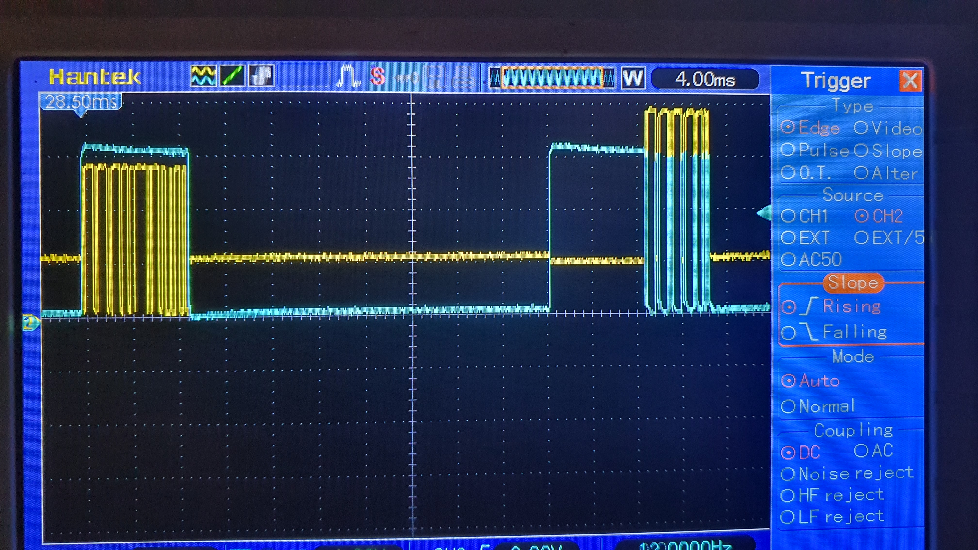
I checked the signals with a scope and do see a request sent and a response:
yellow: RS485 (only B)
blue: Serial 1 Rx
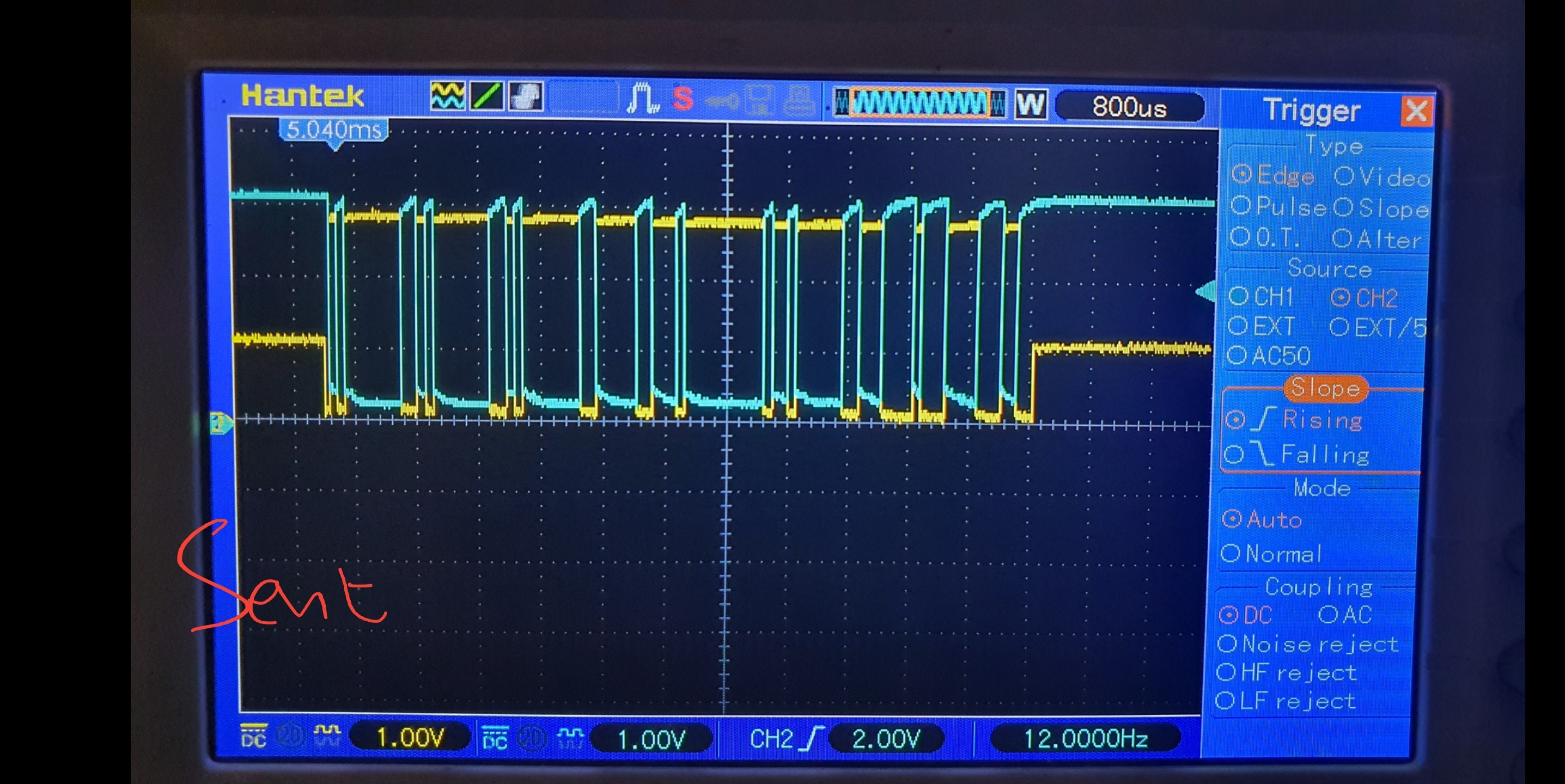
Zoomed in on the sent
yellow: RS485 (only B)
blue: Serial 1 Tx
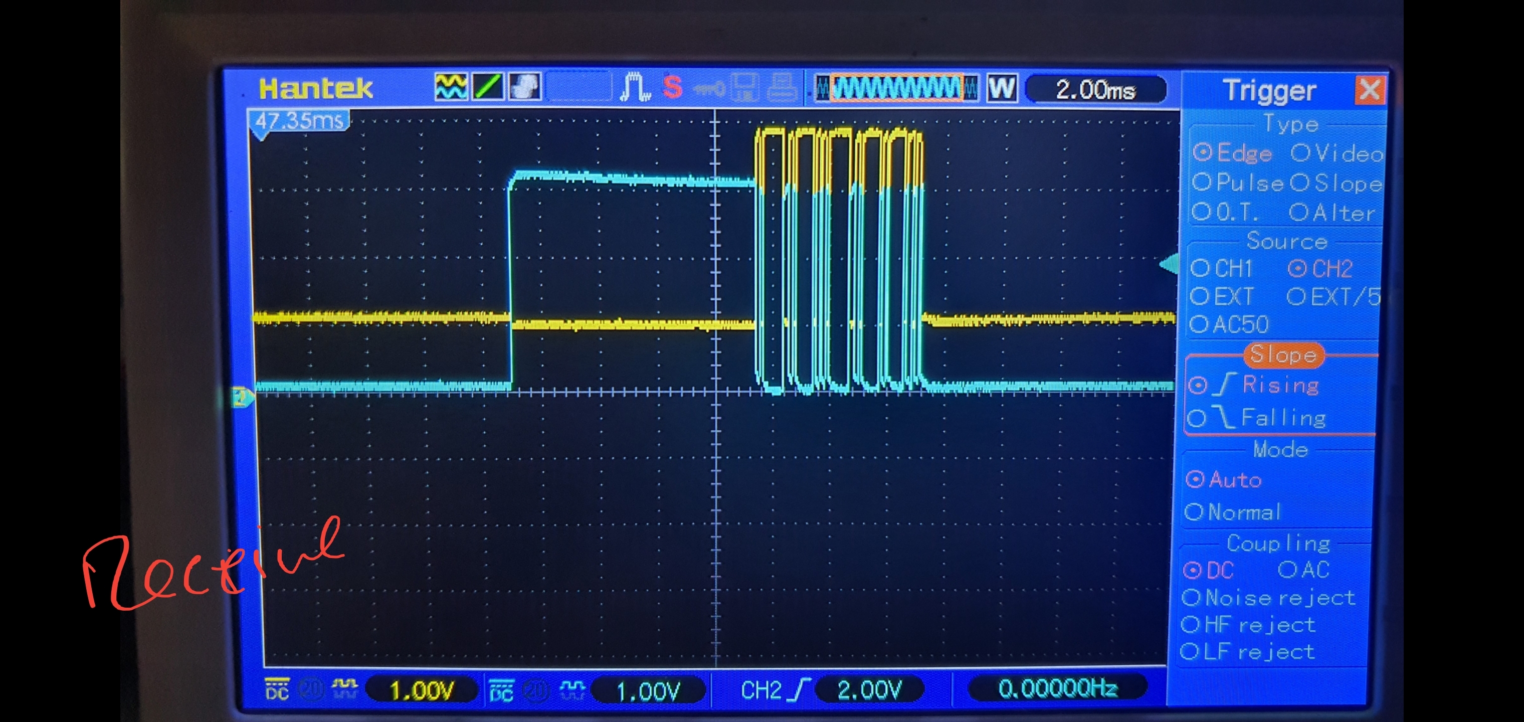
Zoomed in on the receive
yellow: RS485 (only B)
blue: Serial 1 Rx
Any idea where this is going wrong?

The code snippet you showed must be using another library, we do not have a doModbusRequest() call.
Apart from that, a -DLOG_LEVEL=6 as build flag would generate more output to see what is in fact seen by the eModbus lib.
As a long shot I would point to the "leading zero problem" that is known to be caused by some MAX485 adapters.
thx for the awesome fast reply,
sorry, the method is my own wrapper, this is the implementation:
bool ModbusNode::doModbusRequest(Modbus::FunctionCode requestType, uint8_t serverId, uint16_t deviceRegister) {
  uint32_t token = millis();
  //WHY numvalues times 2
  Error err = modBus->addRequest(token, serverId, requestType, deviceRegister, 1 * 2);
  if (err != SUCCESS) {
    ModbusError e(err);
    log_e("Error creating request: %02X - %s\n", (int)e, (const char*)e);
    return false;
  }
  return true;
}
wrt logging I am running it in a larger project and am having some trouble to use the logging setup you have created in the lib (has to do when includes and defines are compiled in the total project). So I manually changed the LOG_D to log_d in your lib.
I think I tracked it down to:
ModbusMessage RTUutils::receive(HardwareSerial& serial, uint32_t timeout, unsigned long& lastMicros, uint32_t interval, bool ASCIImode, bool skipLeadingZeroBytes)
In the IN_PACKET state it determines we are past the interval gap without a new byte which stops the receive.
If this would be cause by the leading zero issue, is there any way to resolve this?
No, if the read is not returning all bytes of the message, that is the "read stall" issue we are trying to fix for a while now (and were not able yet). In unknown circumstances the core read() function will not forward the received bytes from the FIFO to the UART receive buffer any more. Since we are not doing anything other than just call serial.read() in a loop, there must be something happening within the core we cannot see. We had high hopes for the recent improved UART handling in core version 2.0.5 and on, but reportedly the issue still is there even with the new handling that is close to the ESP-IDF now. We were not able to stably reproduce the effect on our devices, though, so we are depending from users' reports like yours.
My current suspicion is some interrupt collisions in the core that only will happen in certain constellations we could not nail down yet.
oke, I can stably reproduce it :-)
I will see if I can troubleshoot it but let me know if I can/have to test something
I would be interested if you are using more than one Serial and if your code does something with pin assignments (the internal routing of the ESP32 I mean). There must be something preventing the core UART interrupt routine from running...
Yes I am running a gsm/gps on HW serial 2 and a nextion display on software serial.
Not sure what you mean with pin routing but I am basically using all pins of the ESP32 for SPI, digital inputs and analog inputs.
But I am afraid I am not experiencing your stall issue.
I added logging all data that is coming in via Serial Rx by adding this just before your receive state machine:
uint32_t start = millis();
    log_d("Read start");
    while (millis() - start < 80) {
      int b = serial.read();
      if (b > -1) {
        log_d("%x", b);
      }
    }
    log_d("Read done");
And now I do see all data that I also see on the scope which also corresponds time wise:
[ 63351][D][ModbusClientRTU.cpp:29] operator()(): rtspin: 1
[ 63361][D][ModbusClientRTU.cpp:29] operator()(): rtspin: 0
[ 63361][D][RTUutils.cpp:270] receive(): Read start
[ 63362][D][RTUutils.cpp:274] receive(): 0
[ 63402][D][RTUutils.cpp:274] receive(): 1
[ 63403][D][RTUutils.cpp:274] receive(): 81
[ 63405][D][RTUutils.cpp:274] receive(): 1
[ 63406][D][RTUutils.cpp:274] receive(): 81
[ 63407][D][RTUutils.cpp:274] receive(): 90
[ 63408][D][RTUutils.cpp:274] receive(): 0
[ 63441][D][RTUutils.cpp:277] receive(): Read done
I also logged the switching of the rts pin and what you see is that immediately after the pin switches I get a "0" on time 63362
then it takes 40 ms before I start receiving data I get back over RS485
As you can see on my scope Serial Rx goes low (which means Serial Rx is not idle anymore) immediately after the rts pin switches to 0
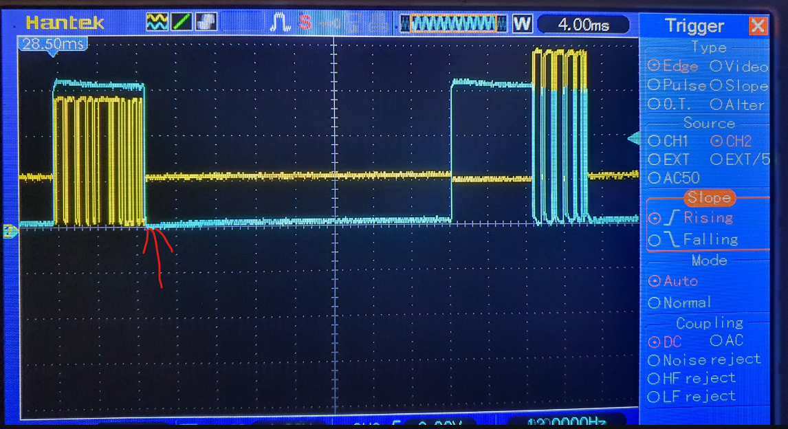
So at the red line the state machine starts reading data but only gets a "0" and then times out as the actual response data comes 40ms later
I found a (I think) similar issue : https://embdev.net/topic/276600
But I think I do have all the pins biased correctly:
found the fix for this
skipLeading0x00(true);
Well, no fix in fact, since that just is gulping up a leading zero byte. This effectively will prevent you from using broadcast requests and is curing a symptom only. The root cause is the spike generated when toggling the RE/DE line that causes the UART to assume a zero being read. As I wrote this is a pattern only some MAX485 adapters are producing. We never had any MAX auto half duplex adapter modules exposing this, by the way.
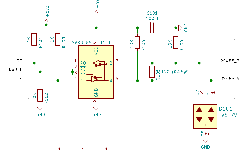
I take it from your schematic that you are using a naked MAX3485 chip and do the external components yourself? The capacitor named C101 is irritating me a bit - will not that create an RC oscillator on the RS485 bus?
aha, this is just a Proof Of Concept so if you can suggest a better 485 IC please let me know.
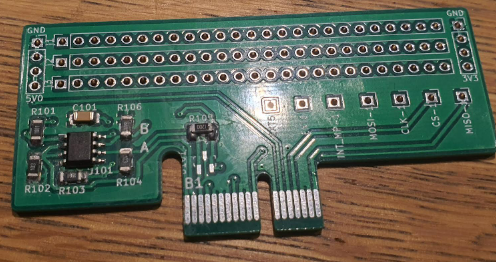
Yes I have the option to add expansion boards to my main board via a PCI slot to test additions
To be honoust I used a schematic I found somewhere else:
https://www.researchgate.net/figure/RS485-module-circuit-schematic_fig4_359561106
I implemented the C as decoupling, not as some filtering, the schematic does not really show that, I changed it to:
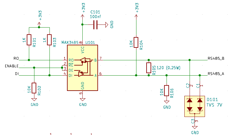
If you have feedback let me know :-)
That looks better to me, but I found exactly the schematic above as well with the C in between A+ and B-, so I might be guessing wrong here.
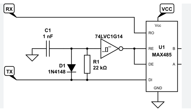
I never had a "bare" RS485 adapter IC myself, so I cannot suggest anything better. But as I wrote the modules with auto half duplex never showed that effect, whereas all experiencing it had deployed some with DE/RE toggle lines. It may be worthwhile to study the schematics of the automatic modules to find how these are avoiding the toggle peak.
with auto half duplex you mean you do not need the rts pin?
Something Like this?
Yes. I googled a bit and found the MAX13487E and MAX13488E chips providing this.
ah nice, quickly scanned it, seems like a good option with fewer components
(allthough this is a 5V IC, ideally for the esp32 a 3v3 ic would be better as it does not need level shifters)
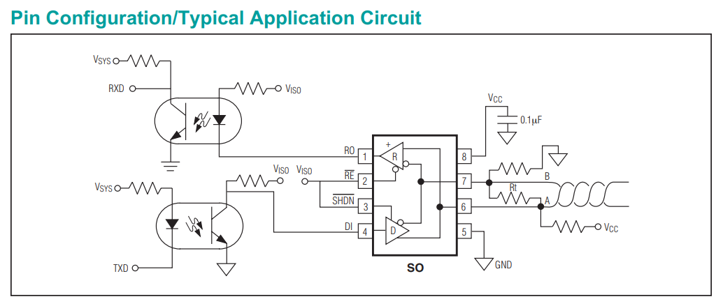
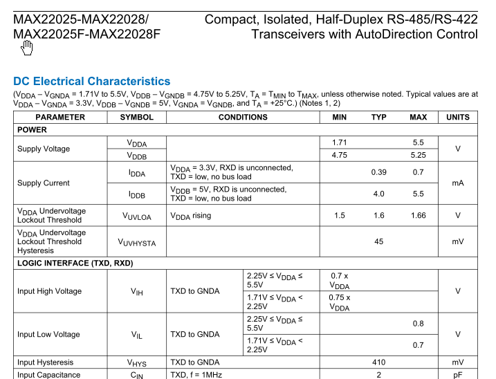
Looks like there is a range of MAX chips supporting 3V3 signals while needing to be supplied with 5V only: MAX22025/26/27/28 and MAX22025F/26F/27F/28F:
mostly out of stock till feb 2023 :-(
But topic this has really helped me.
THX!!
The issue is still valid, but covered by another issue (#198) to be kept on the list.