


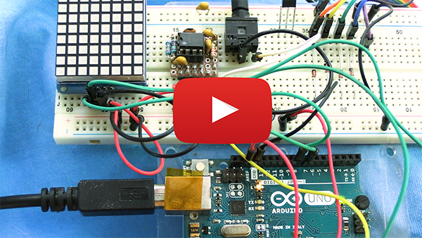
Spectrum analyzer display using MSGEQ7, 8x8 bicolor matrix and Arduino Uno. Input is from a head phone jack or microphone.
Short but powerful.
Clone the repository and its submodules to a local directory. The --recursive flag automatically initializes and updates the submodules in the repository.
git clone --recursive https://github.com/cvonk/MSGEQ7_8x8matrix.gitor using ssh
git clone --recursive git@github.com:cvonk/MSGEQ7_8x8matrix.gitThis project uses input from headphone input or amplified microphone and outputs to a 8x8 bicolor matrix.
Power

Logic

A few notes:
- The 200 kΩ resistor is not an E12-series value. You can also make an equivalent value by 220 kΩ and 2.2 MΩ in parallel, or put two 100 kΩ in series.
- If there is noise, try adding a 47 μF across the power rail.
- I put the MSGEQ7 and its glue on a piece of proto board.


Make sure the MSGEQ7 is authentic. It should draw about (0.8,\rm{mA}); pin 6 should have a reference voltage of about (2.5,\rm{V}) and have an indentation near pin 1.
| Name | Description | Suggested mfr and part# | Paid |
|---|---|---|---|
| PCB1 | Arduino Uno R3 or compatible | Adafruit 2488 | $17.50 |
| PCB2 | Bicolor LED Square Pixel Matrix w/ I2C breakout | Adafruit 902 | $15.95 |
| PCB3 | Electret microphone w/ auto gain control | Adafruit 1713 | $7.95 |
| U1 | Seven Band Graphic Equalizer Display Filter | MSI MSGEQ7 | $5.50 |
| J1 | Headphone jack stereo connector, 3.5mm, kinked pin | Kycon STX-3120-5B | $0.74 |
| R1, R2 | Resistor, 22 kOhm, 1%, 1/8 W, 0805 | Yageo RC0805FR-0722KL | $0.10 |
| R3 | Resistor, 200 kOhm, 1%, 1/8 W, 0805 | Yageo RC0805FR-07200KL | $0.10 |
| C1, C2, C3 | Ceramic capacitor, 0.1 µF, 25V, 0805 | KEMET C0805C104M3RACTU | $0.10 |
| C4 | Ceramic capacitor, 33 pF, 50V, 0805 | KEMET C0805C330J5GAC7800 | $0.10 |
The popular Arduino UNO R3 forms the heart of the system. This board is now getting hard to find, but you can also use the Arduino METRO 328 or any other equivalent boards.
For the microphone, I use the Adafruit microphone breakout, because includes an automatic gain control. Other microphones will work for as long as the output signal is strong enough.
The implementation changes the sound wave to an electrical signal; uses autocorrelation to find frequency played; display frequency as note on screen while sending to a MIDI synthesizer.
| Component | Version tested |
|---|---|
| Arduino IDE | 1.8.19 |
| Arduino AVR Boards | 1.8.5 |
| Adafruit LED Backpack library | 1.3.2 |
| Adafruit GFX library | 1.11.1 |
- Install the libraries.
- Using the Arduino IDE or Visual Code
- Specify the board and COM port.
- Build and upload the sketch .
The MSI MSGEQ7 measures the peak voltage in 7 frequency bands. These voltages are multiplexed on one output pin. The timing is shown below, and includes some corrections compared to the datasheet Maxfield.

To read each value, we use the RESET and STROBE* pins.
- A
RESETpulse followed by a wait (≥72 μs) resets the multiplexer. - On the first falling edge of the strobe signal, the 63 Hz band output propagates to
OUT. After ≥36 μs, this analog value can be read by the host. - Each additional strobe falling edge advances the multiplexer one frequency band (63 » 160 » 400 » 1,000 » 2,500 » 6,250 » 16,000 Hz) and this will repeat indefinitely.
Each read operation decays the value of that frequency band by approximately 10%. This means that if the Arduino reads less often, e.g. as a result of doing computations, the values read will be higher.