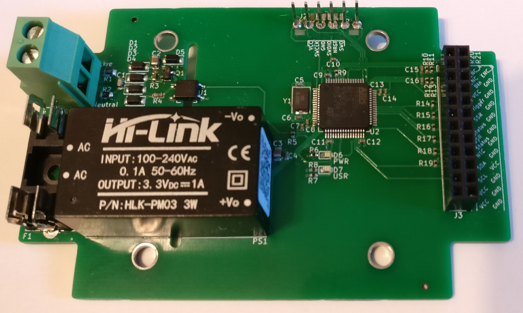
ZCSSR - Zero crossing solid state relay controller
A PCB and software for a SSR controller that monitors mains AC zero crossings to determine when to turn the SSR on.
Why
I wanted to build a spot welder from an old MOT (microwave oven transformer) but wasn't satisfied with simply enabling the SSR at random because this makes the pulse +/- 1 half mains cycle (10ms on 50Hz, 8.3ms on 60Hz). It probably doesn't make much difference in the grand scheme of things but I wanted to know exactly how long the pulses were.
This controller solves that issue by monitoring the mains zero crossing and triggering the SSR just before a zero crossing - the SSR has it's own zero crossing circuit to actually turn on it's output so as long as the controller doesn't fire more than 1 cycle early it will work as expected.
I also wanted to completely finish an embedded project written in rust and this project seemed about the right size undertaking.
Uses
- Spot welder
- Reflow oven
- Sous vide
- Smoker
- Probably other things that need temp input (K-Type thermocouple) and switched mains ouput
Features
- Zero crossing detection circuit
- Pulse at least 0.4ms before the zero crossing
- Isolated
- 100-240V, 50/60Hz
- Details
- UI
- Quadrature encoder with push button
- LED for general status
- LED for SSR status
- 4 digit 14-segment LCD display. I2C
- Trigger input
- Temperature monitoring
- NTC thermister for monitoring SSR/Transformer temperature
- K-Type thermocouple input. MAX31855
- STM32F1 64-pin LQFP MCU. Specifically STM32F103RCT but any should work
- SWD (serial wire debug) programming & debugging
- USB hardware. In theory USB programming will be possible but not yet implemented
Tools used
Not a complete list. Will add to it as features get implemented
Documentation
Getting started
- Clone the repo
- Run
./bootstrapscript which will:- Initialize git submodules
- Run
firmware/bootstrapwhich will:- Checks if OS dependencies are installed
- Currently
gcc,gdb,openocdandlibudev-dev sudo firmware/install_apt_depswill install these deps if you are using a distribution that usesapt
- Currently
- Install or update rustup
- Install required rust embedded toolchains
- Install utils from crates.io
- cargo-binutils
- cargo-watch
- llvm-tools-preview
- serialitm
- Run a cargo check, build and doc of the firmware (will take quite a while the first time)
- Checks if OS dependencies are installed
- Direct flashing the the device
firmware/deploy_standalonewill start openocd, flash the program and restart the device
- Debugging with gdb
firmware/run_openocdin one terminalfirmware/releaseorfirmware/debugto build and launch gdb- Take a look at
firmware/openocd.gdband the scripts above to tweak the behaviour
- Log output
- Firmware built with
--feature itmwill log over SWD firmware/monitor_itmwill launchserialitmto print this output with the ITM control characters stripped out. You may need to tweak the script if your uart dongle isn't/dev/ttyUSB0
- Firmware built with
- Tmux
firmware/tmux_workspaceis a script that will open a tmux session withfirmware/run_openocd,firmware/monitor_itmandfirmware/watchin differnt panes to make development easy. Just type./releasein one of the spare panes to deploy the software with gdb
ITM logging
The code uses ITM logging to indicate start up progress and log info like temperatures and user config. If the ITM feature is enabled, the microcontroller won't run without openocd connected because there is some debug config openocd does to the chip that makes ITM work. I've added the obvious checks to the itm_logger crate but there's still something missing that I haven't got to the bottom of yet. There's an issue to track it. The bottom line is if you want to be able to plug the hardware into the mains without OpenOCD connected you need to disable the itm feature (firmware/deploy_standalone already does this.)
More info
Check the docs folder for information on setting up the dev environment and various info on making the hardware.
Mains warning
- Mains is dangerous, see the disclaimer
- A specific issue you might hit is powering the device over USB during development then plugging the mains in while the USB dongle is still attached. The mains will power the AC/DC on the board and that will backfeed 5v into the 3.3v/5v provided by the dongle. It's fine to leave the dongle connected if you disconnect it's 3.3v/5v line - only ground, swd, swclk should be connected to the ST-LINK if you want to plug the mains in. The UART connected to ground and swo is also fine. If you do backfeed 5v to the ST-LINK expect the ST-LINK to break as a minimum and the USB port it's connected to as a worst case.
Disclaimer
- This project uses mains electricity and will kill you if you handle it improperly
- You are responsible for your own safety
- Despite best efforts the author makes no guarantees that this design is safe, fit for purpose or meets any quality standards
- If you decide to build this or a similar device you must understand and take necessary safety precautions before proceeding
- The author cannot be held responsible for any damages or any form of loss that comes as a result of using any information found in this project
License
This template is licensed under either of
-
Apache License, Version 2.0 (LICENSE-APACHE or http://www.apache.org/licenses/LICENSE-2.0)
-
MIT license (LICENSE-MIT or http://opensource.org/licenses/MIT)
at your option.
