ECE385FinalProject
Made with <3 by Brandon Qiao (github.com/bqia0) and Skyler Shi (github.com/icarusoars)
Introduction
For our final project, we implemented a drawing canvas that allows users to perform free-form drawing with a handheld laser pointer. By using Altera’s DC2 camera module and the provided Verilog code on Altera’s website to interface the camera, we configured our camera to be able to track the laser pointer dot. Then we used the position information of the dot as an input to draw different colors onto the VGA monitor. The result is our final project – a free-form drawing canvas.
Design Choices
When we were coding our final project, we made several design choices that ultimately impacted our final product. First of all, we decided to use on chip memory to store our frame buffer instead of the bigger SDRAM & SRAM. This is because we had much difficulty interfacing with the SDRAM & SRAM. By using OCM, we were able to represent less colors, but encountered much less timing issues than using SDRAM or SRAM. Second of all, we encountered issues in the conflicting widths in signals between our design and Altera provided code. For example, Altera’s camera module CCD_Capture outputs pixel coordinates as 11 bits whereas our framebuffer only has enough memory space for addresses of 10 bits. In such a scenario, we decided to truncate the 11 bits outputted by the CCD_Capture into 10 bits by taking the 10 most significant bits. We performed experiments and confirmed such a practice does give us the correct pixel coordinates and the expected output. Lastly, to initialize the frame buffer so we get a blank canvas, we decided to read from a textfile hex color values instead of using a system Verilog for loop to instantiate all memory spaces in the OCM frame buffer. This is because compiling the for loop for all the memory spaces takes very long and makes it very hard to debug the circuit. Hence, we chose to load frame buffer hex color values from a text file. The trade-off is that the frame buffer cannot be easily reset without an entire system reset.
Operation of Drawing Canvas
The camera is pointed to a flat surface. Switches [15:0] on the board are used to adjust the exposure amount of the camera. The red laser pointer moves the cursor on the VGA screen and when it is turned off or moved off screen the cursor remains in its last registered position. Switches [17:16] are used to toggle the four different colors users can draw from – white, black, red, blue. Key2 on the board is the draw button that draws pixels of the selected color at the cursor position when pressed.
High Level Description
Module Descriptions
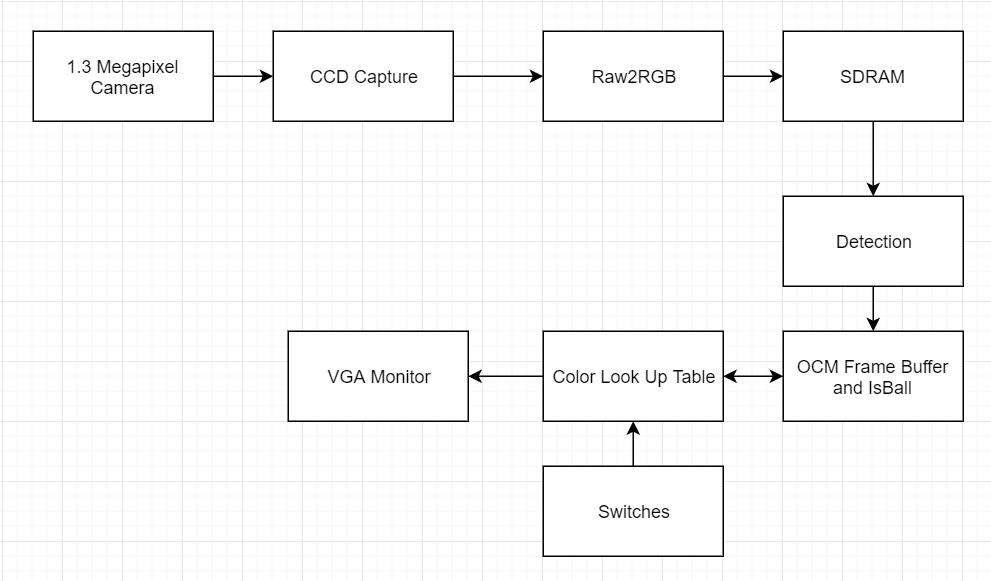
CCD_Capture
CCD_Capture is the Altera provided module that accepts camera image input as a 10 bit array and organizes that data into data for each pixel that is 10 bits.
Raw2RGB
Raw2RGB is the Altera provided module that accepts pixel data outputted by CCD_capture and translates it into RGB values and then outputs them.
Detection
The detection module is responsible for finding the coordinates of the laser. It takes data generated by Raw2RGB and finds the pixel with the highest red value. It then outputs the coordinate of this pixel. Each pixel must have a minimum red value (arbitrarily set to 10’d750) to be considered. This way, we were able to eliminate much of the noise coming from the camera that made our tracking jittery and imprecise. This module works in a way such that each frame only has one “most red” pixel. Thus, at 60 frames per second, one can expect 60 changes in coordinates per second.
OCMFrameBuffer
The OCMFrameBuffer module is the interface for writing data into and reading data out of the on-chip memory frame buffer. The on-chip memory is also instantiated in this module. Since the VGAController we are borrowing from lab is drawing 800 * 525 pixels per frame, we allocated 800*525 = 420,000 locations of on-chip memory. We used 2 bits for each memory location, so we can represent a total of four colors in memory. Initially, we opted to read out data from the frame buffer at a clock speed of 25MHz, the same clock speed as the VGA clock. Our rationale behind choosing this clock to read out frame buffer data was that our frame buffer data-out would be in sync with our VGA controller. To write data into our frame buffer, we used the system’s 50MHz clock. However, observations showed that the drawing functionality was a little bit laggy, so we instantiated a higher frequency PLL clock at 100Mhz, and drove both reading and writing into our frame buffer with it. Results showed that drawing was much smoother. It is also important to note that not everything on our VGA screen goes through the frame buffer. All the lines and dots drawn by the user are stored in the frame buffer, but the cursor and the color palette displayed by the VGA screen are only fixed function drawings. This is because bother the cursor and palette are geometric objects that have a pattern, unlike the pixels being drawn by the user. OCMFrameBuffer module instantiates a modified isBall module (from Lab 8) and identifies whether the pixel being read out is part of the ball representing the cursor. This information is sent to Color Look Up Table module to properly color the cursor. Also, the OCMFrameBuffer identifies whether the pixel being read out is part of the color palette and color palette border located on the bottom left corner. This information is also sent to Color Look Up Table for proper coloring. OCMFrameBuffer does not keep track of which pixel is being read out or which pixel is being written in. Which pixel is being read out is determined by the VGAController, which outputs whatever pixel is being written to the monitor at an instant. Which pixel is being written in is determined by the Detection module, which outputs whatever pixel the laser pointer is pointing to at an instant. Color Look Up Table Since On-Chip Memory only stores 2 bits per pixel, the full RGB data cannot actually be stored into memory. Thus, we map the RGB data into 2 bits long and store the 2 bits into on-chip memory. Color Look Up Table serves to translate the 2 bits into meaningful RGB data to output to the VGA monitor. The encoding for our colors is the following: 00: white, 01: black, 10: red, 11: blue. This module takes in the switch input values and sends in the corresponding color to OCMFrameBuffer to store away into the frame buffer. This module also takes in the output data from the OCMFrameBuffer, translates the 2 bits into VGA red, green and blue data, and outputs them to the VGA. Also, this module outputs the color of the cursor or the color of the color palette when the VGA controller is drawing the pixels that correspond to the cursor and color palette.
VGA Controller
This is the module from lab 8 that controls the signals needed to drive the VGA. We did not make any modifications to this module. For our project’s purposes, the VGA displayable area is still 640 * 480 and including the front and back porches, the VGA spans 800 * 525 pixels. All the horizontal and vertical sync signals are also left unchanged.
Demonstration

Further Steps
As results from the demo showed us, even with a faster clock of 100MHz, the pixels are being drawn at a rate too sparse. What should be connected lines do not seem like connected lines. Since on chip memory is very fast and it is being read and written into at speeds of 100 MHz, our theory is that the camera is not sending enough frames, making the detection of our laser pointer dot happen more infrequently than we would like. Our solution to this is to employ Bresenham’s algorithm, which is an algorithm colors the correct pixels to form a line between two pixels. To do this we would have to record the pixel coordinates of the pixel previously drawn and the pixel being drawn and then employ the algorithm to color all the pixels in between them to form a line. Doing so would make our laser drawing form coherent lines instead of the dots we see now despite the suspected camera hardware limitation. Another step we wanted to take was to let the user be able to select different widths to draw from. This would require detecting which direction the user is drawing from and coloring the pixels vertical to the direction of travel.
Conclusion
In this final project we implemented a minimum laser-pointer driven drawing canvas. The idea is to allow the users to be able to draw more naturally than using a mouse or other form of input. We read into depth how to interface the DC2 Altera camera module, which had rather poor documentation. We also spent a lot of time trying to implement a frame buffer with SDRAM and SRAM, but we failed to do so. This wasted a lot of our time for the final project. If we had more time, we would have implemented the features mentioned in further steps. However, despite the deficiencies, we feel like this is a useful product that can be improved to be much more impressive with more time.