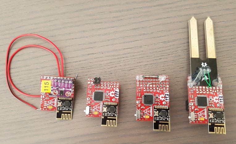
This sensor node was designed to be used in the MySensors dollhouse display, created for the Eindhoven Maker Faire 2017
- Very small, so it can be mounted visible in the house without distracting too much
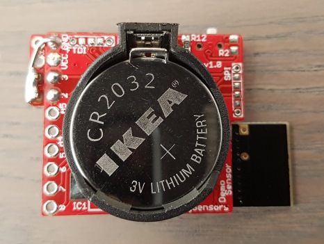
- 5V supply, or battery powered (CR2032)
- runs at 3V3
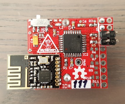
- nRF24L01+, SMD version
- 8MHz, internal oscillator
- Optional buffer cap (47..100uF) for battery node
- ATMega328; cheap, stay close to well known Arduino UNO/Pro mini
- ISP connector; small, ProtoProg
- Serial connector; small, pogo pins, GND, RX, TX, DTR (reset)
- At least 1 sensor per node
- On/off switch (for battery sensors)
- Application LED (Pin 4)
- Power LED (d.n.p. for battery sensor)
- IO to support sensors
The resulting node is very small (28.5 x 25.5mm, excluding antenna) and costs roughly E4,30/piece (excluding sensor)

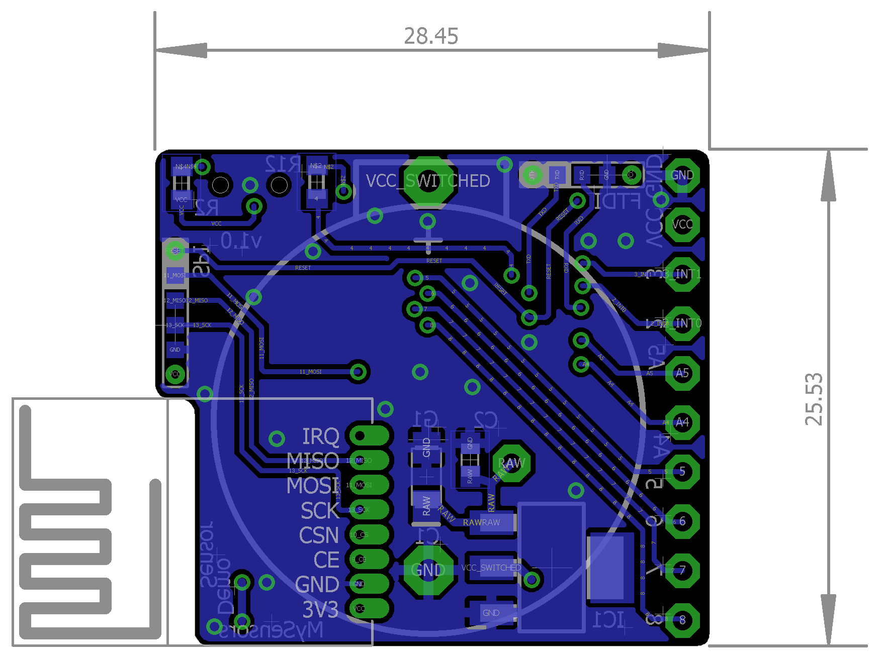
| Pin | Arduino Pin | Alternate Function |
|---|---|---|
| 1 | GND | |
| 2 | VCC | |
| 3 | 3 | INT1 |
| 4 | 2 | INT0 |
| 5 | A5 | I2C SCL |
| 6 | A4 | I2C SDA |
| 7 | 5 | |
| 8 | 6 | |
| 9 | 7 | |
| 10 | 8 |
Pin 1 is next to the FTDI pogo pin connector.
I created a small addon board to simplify connecting a numer of standard sensors. It can be mounted on the IO connector using male headers. Supported sensors/actuators:
- 2 servo's
- AM312 Mini PIR
- BME280 Temperature, relative humidty & pressure sensor
- APDS9930 Digital Ambient Light and Proximity Sensor
- APDS9960 RGB & gesture sensor Please make sure to verify the pinout and supply level of a module before connecting it to the addon board!
Small 10 x 4 proto board to connect other sensors (e.g. the soil humidity & wind-speed reed sensor)
Start with the ATMega, followed by the small SMD's on the top and nRF24. Flip the board and mount either the CR2032 holder, or the AMS1117-3V3.
The switch is optional. Either mount the switch or short solder jumper SJ1.
Mount the power LED (and its resistor R2) if you prefer a visible indication of a node being switched on. Do not mount it on a CR2032 powered sleeping node as it will drain the battery too quickly.
Pull-up resistors R4-R11 can be used for digital inputs to further reduce the power drain. Mount approx. 1Meg ohm and disable internal pullups.
When powered from a 5V supply (and AMS1117 mounted) use the RAW and GND pins to power the board.
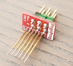
To keep the sensor small the ISP and FTDI connectors are scaled down to use pogo pins for programming. ISP programming requires a ProtoProg adapter.
To flash the bootloader refer to my Ikea Molgan Hack
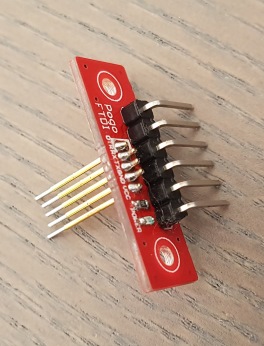
The serial connection used by the Arduino IDE is available at a 5 pin FTDI-to-pogo adapter, also included in this repository. Make sure to align the white pin on the adapter to the white pin on the board. I use the node's power when programming at 3V3 serial levels.

- The buffer capacitor C4 is located after the switch. Powering off a sleeping sensor will take some to actually shut down the sensor as the buffer capacitor will still supply the ATMega for some time.