HalfEdge structures holding colors on edges -> how to subdivide such mesh? + documentation question
StefanEvanghelides opened this issue · comments

Hello,
I am conducting a research in which I am analyzing the feasibility of using OpenSubdiv to subdivide a mesh, considering the following:
- a Mesh consists of 3 arrays: Vertices, Faces and HalfEdges
- the structure of the 3 components is as follows:
- Vertex: coordinates (obviously), HalfEdge pointer to 1 edge going outwards + others (edge valency, index)
- Face: HalfEdge pointer to 1 edge of the face, valency, index
- HalfEdge: 3D vector for color (!! important), bool for sharpness (!! important), target Vertex pointer, next HalfEdge pointer, previous HalfEdge pointer, twin HalfEdge pointer, Face pointer and index value.
- the bolded fields of the halfedge are highly important because they allow for sharp color transitions at any level. Another requirement which uses these 2 fields is hierarchical editing, the idea being that higher subdivision level would allow for a finer level of detail to be applied by the user on the mesh.
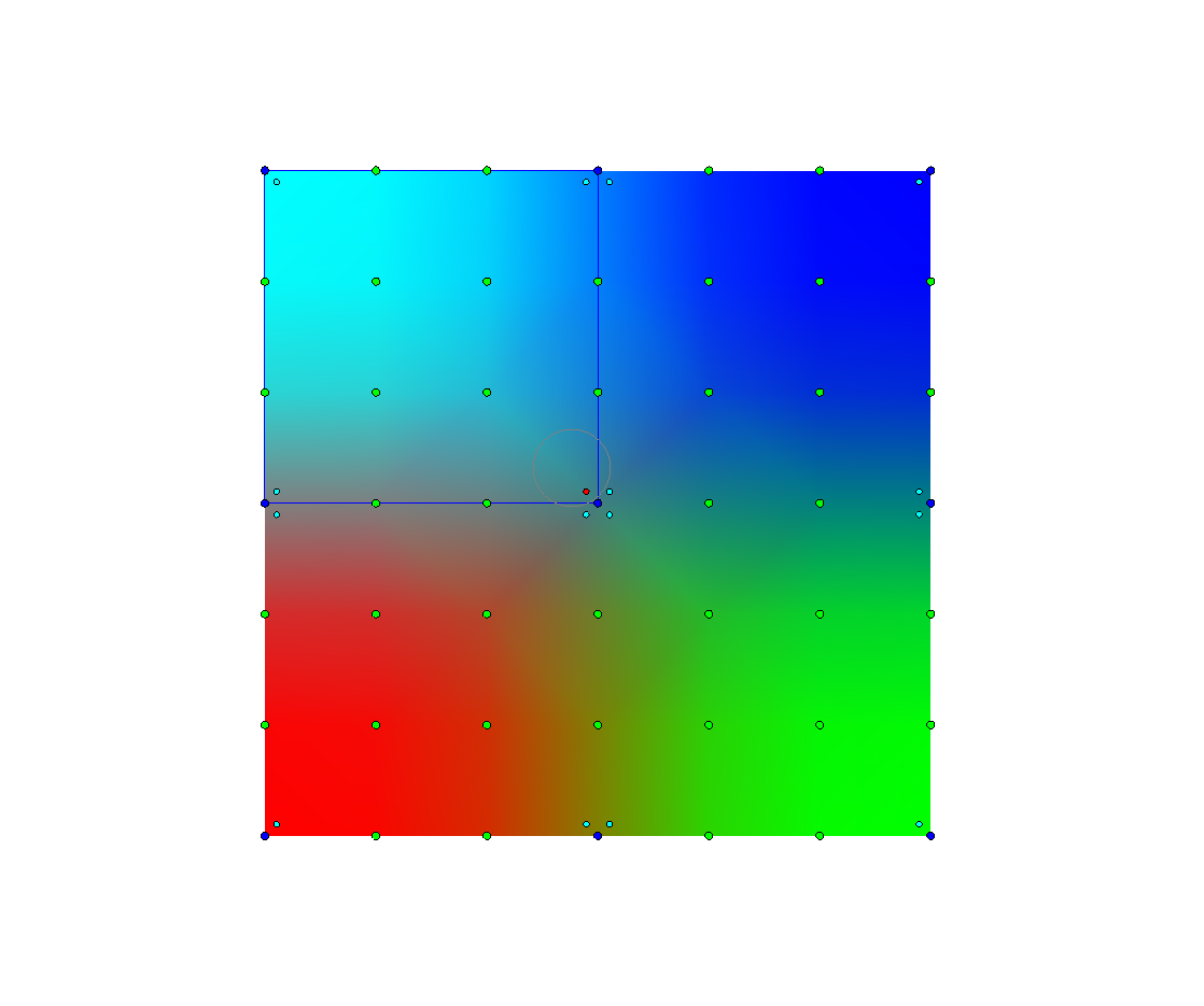
As an example about the color editing mechanism, see the figures shown below. In Figure1, it shows a simple mesh of a square split in 4. The cursor is pointing at the middle vertex, towards the top-left face. Changing the color is done by selecting 1 of the 4 small dots near the mid vertex. Figure 2 shows the power of colors attached to halfedges: only the corner of the top-left face had the color interpolated.

I have therefore several question:
- is it possible to subdivide such a mesh structure? if so, how? My current idea is to convert such mesh into the Descriptor data, refine vertex positions (I tried both PrimvarRefiner and StencilTable), then try to reconstruct the HalfEdge structure. As you can image, this process is very slow and thus unfeasible for subdivision level > 2.
- I noticed that Hbr is now deprecated. I had a quick attempt to potentially use this, but dropped the idea because the conversion to HbrMesh was also cumbersome.
- another idea that I am currently trying is to have a Custom Topology Refiner class. I am currently working on the Converter. While this method seems a little bit more promising, I believe it may still not be sufficient, because I lose the important fields during the conversion. I am following tutorial 3 for this and trying to fill in the data in those fields, but currently it seems that it's not very easy for HalfEdges. My best estimate (which is what I am working on right now) is that they require an additional converter class into full edges (I called them OsdEdge). I am still (re)considering the mesh's design using these edges, but most likely the new structure would have fields such as:
- Vertex To
- Vertex From
- HalfEdge To (mainly for the 2 properties)
- HalfEdge From (mainly for the 2 properties)
- index
Any pointers would be highly appreciated.
Also as a side note:
Tutorial 3 (with the custom topology refiner) mentions the existence of a file called hbr_to_vtr.h, but I couldn't find it in the source code. Was it removed/renamed?

To answer your last question first: the file in question is still in the repo along side the tutorial source: hbr_to_vtr.h
But you are correct that Hbr is now deprecated and we don't recommend starting a new project which depends on it.
Have you had a chance to look into OpenSubdiv's support for face varying data and topologies?
This seems closest to one aspect of what you are trying to achieve, i.e. representing a sharp discontinuity for a signal like color along the shared edge between two faces defining a smooth surface. Most of the discussion around face-varying data describes u,v texture coordinates since the most common use case is to use a face-varying representation to allow for the seams that can occur in an u,v unwrapping of an object, but everything works equally well for any signal, e.g. like color.
We've also removed specific support for hierarchical edits. Though if you are interested in exploring that topic you can take a look at how hierarchical edits were implemented in Hbr.

Filed as internal issue #OSD-355
Thank you for your quick reply.
Regarding the hierarchical edits, I found 2 ways to do so:
- either reinitialize the topology at each level (so set maxlevel=1 and call it for every subdivision level), using primvar data, but then this obviously defeats the purpose of splitting topology from vertex data.
- use cascading Stencil tables, as shown in Tutorial 4.3: presume that this is the method
Regarding face varying data, I've had a quick look before, but I was not sure that this would help. Looking at it again, it does seem to be the closest to my needs. I have thus 4 questions:
- Am I correct to assume that this method potentially duplicates the edges in order to allow discontinuities?
- What is actually the UV channel (as showin in tutorials 2.2 and 2.3). My first impression is that this is for a local vertex location within a face. I notice that there are 3 interpolations done in the following order: for vertex position, for UV and for color, so I am trying to understand what the UV is here.
2b. If I understand tutorials 2.2 and 2.3, is setting such signals done by the following:
  // (specify g_colorIndices in the colorChannel before)

...

        fvVertsColor[i].r = g_colors[i][0];
        fvVertsColor[i].g = g_colors[i][1];
        fvVertsColor[i].b = g_colors[i][2];
        fvVertsColor[i].a = g_colors[i][3];
- Is it possible to achieve this using Stencil Tables? If so, how?

I'll add some information and answers about face-varying data first and follow up with the original questions about topological representations later...
If you want discontinuities in data assigned to your mesh, as David notes, that is best achieved using face-varying data -- and your assignment of color to your half-edges and your interaction with it is essentially doing this (so when you say you are "not sure that this would help", I'm optimistic that it will).
The page of documentation for face-varying that David cited (here again) does illustrate the answer your second question about the purpose of the UV channel in tutorials 2.2 and 2.3 -- the UVs being used for texture coordinates.
To answer your first question, discontinuities are not represented by duplicating edges of the mesh. The topology of the mesh with respect to edges is fixed regardless of how many face-vary channels exist and what edges might be continuous. A face-varying channel contains the data indices assigned to each face vertex and additional internally assigned tags indicating whether that data is continuous or not wrt the mesh topology. Those tags are internally used to decide how face-varying values are to be subdivided (and can be publicly queried if desired).
This is essentially what you are doing by adding a color field to your half-edge with an associated sharpness tag to indicate its continuity. Assigning color to half-edges is equivalent to assigning them to the face-vertices, so you have defined what OpenSubdiv considers a set of face-varying data (and the interface you provide to users has them interacting with values at face-vertices). If you were to add another field to your half-edge (say a UV texture coordinate) and an associated sharpness tag for its continuity, you are essentially adding a second face-varying channel -- without impacting the primary half-edge topology of your mesh.
The difference between your half-edge representation and the TopologyRefiner is that that the TopologyRefiner completely decouples the data assignment from the topology, and in doing so, the TopologyRefiner allows for an arbitrary number of face-varying channels to be defined relative to the mesh topology (each with independent continuity). The topological data for TopologyRefiner is stored in more as a structure-of-arrays form rather than an array-of-structures, and face-varying channels are simply additional arrays that can be optionally added to that structure without impacting it in any way.
One issue you are likely to run into is that your color values are stored explicitly with the half-edge, rather than using separate indices to color values that are either shared or distinct across edges (as shown in the documentation example). In OpenSubdiv and other applications, continuity of face-varying data is determined implicitly by the use of indices to these shared or distinct data values.
So when you create a face-varying channel you will need to convert your color values into a set of distinct data values -- the number of which will typically differ from the number of vertices when discontinuities are present. These distinct values must then be assigned to each face-vertex by index in order to be effectively processed by OpenSubdiv. This is a common requirement when representations choose to store their face-varying data explicitly by value for each face-vertex (and there are often good reasons to do so). Fortunately for you, you have already encoded the continuity of color with the half-edge, otherwise explicit comparisons of values becomes necessary to determine continuity (this is still done with texture coordinates in some widely-used applications).
Finally, for your third question, a StencilTable can be created for re-computing a set of face-varying values resulting from subdivision just as it can for a set of vertex values. I see now that the set of tutorials for StencilTables (4.x) does not include an example of a face-varying StencilTable, but constructing it is almost identical to what is done for the vertex and varying tables in 4.2: you just need to specify in the set of Options that you want the table to be created for a specific face-varying channel, and then be sure to use the appropriate sets of face-varying data with that table.
Hopefully that helps clarify and steer you towards a face-varying solution.
I'm hesitant to raise the topic now, but at some point you will need to decide how you want your color values to be subdivided/interpolated at the discontinuities. Several choices have arisen over the past decades (some more practical than others), which are illustrated in the "Face Varying Interpolation Rules" section of the documentation that outlines the various subdivision options. The choices range from completely smooth subdivision to purely linear -- with variations in between that apply linear constraints along the discontinuities.
Thank you for the detailed answers! This was very helpful!
I believe this issue can be closed now, but I will let you do this when desired, since you filled an internal issue out of it.
Sounds good. Thank you all!