Submission Folder: project_file
Submission file:
firmware.bin
- Attention for Submission
- 1. Embedded System Coursework 2 - Group Hex Future
- 1.1. Core Functionality and Specifications
- 1.2. Identification and Summarisation of Tasks
- 1.3. Critical Time Analysis with Initiation Intervals and Execution Time with Quantification of CPU Utilisation
- 1.4. Shared Data Structures and Methods for Safe Access & Synchronisation
- 1.5. Analysis of Inter-Task Blocking dependencies
- 2. Advanced Features
The following section will descript the core functionality requested by the specification document.
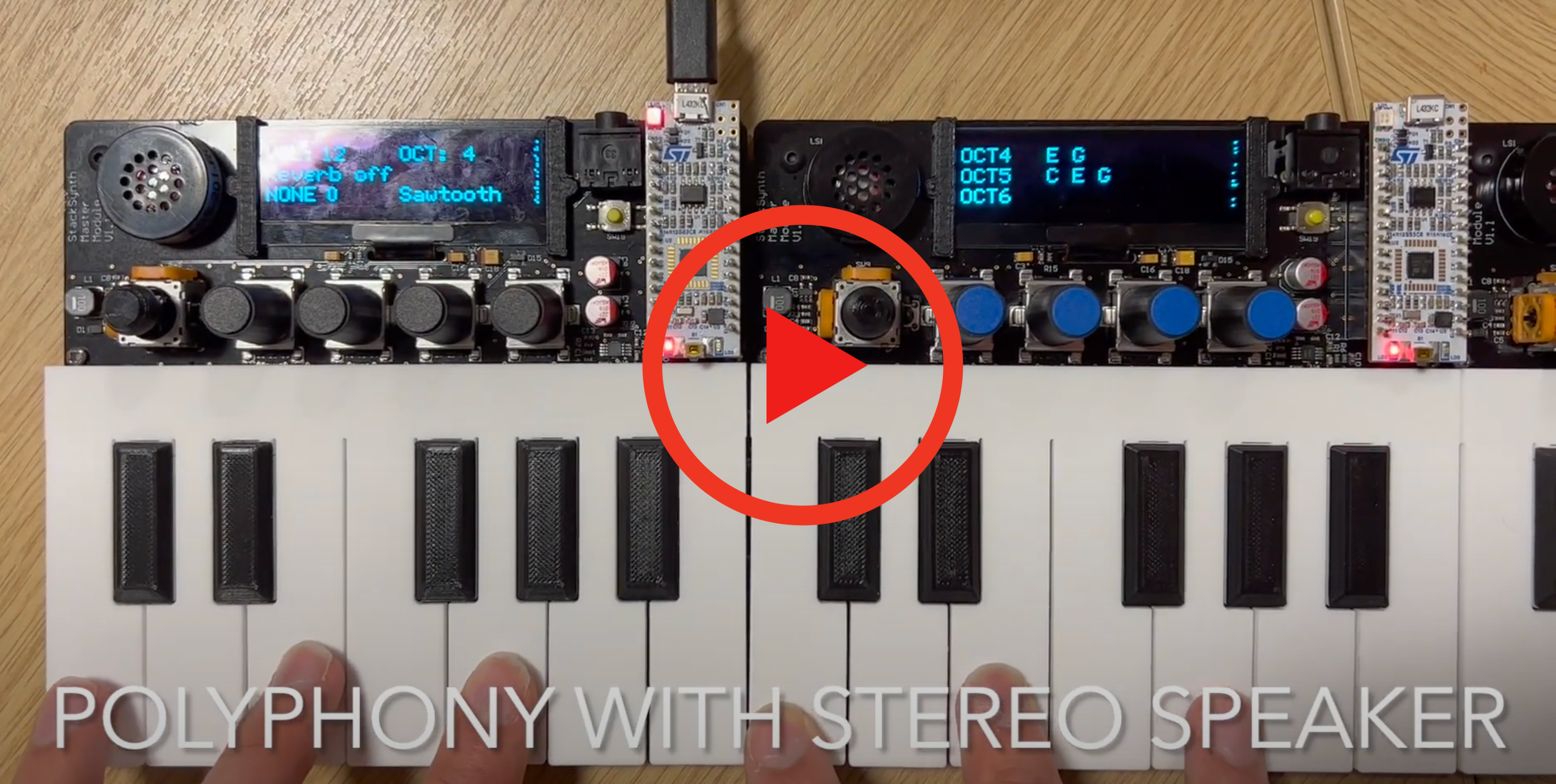
URL: https://youtu.be/liQCLkLKoVk
SampleISR: Produce notes in different waveforms in response to different key press
CAN_DecodeTask: Decode messages related CAN communication for transimission purpose
CAN_TxTask: Transmit CAN bus messages for notes' change and other functionality setting changes.
DisplayTask: Display information about music synthesiser setting in real-time
ScanKeysTask: Read any changes in inputs and update the variables
Overall, 1 interrupt and 4 threads are used for the music synthesiser. Table 1 below summarise the tasks with type and priority.
| Tasks | Types | Priority |
|---|---|---|
| SampleISR | Interrupt | Highest |
| CAN_DecodeTask | Thread | 1 |
| CAN_TxTask | Thread | 2 |
| ScanKeysTask | Thread | 3 |
| DisplayTask | Thread | 4 |
Table 1: Summary of Tasks with Types and Priority
1.3. Critical Time Analysis with Initiation Intervals and Execution Time with Quantification of CPU Utilisation
| Tasks | Execution Time, Ti | Initiation Interval, τi | [τn / τi ] * Ti | Ti / τi |
|---|---|---|---|---|
| SampleISR | 13 μs | 45.45 μs | 28.6 ms | 28.6% |
| CAN_DecodeTask | 16 μs | 25 ms | 0.064 ms | 0.064% |
| CAN_TxTask | 21 μs | 30 ms | 0.07 ms | 0.07% |
| DisplayTask | 18.5 ms | τn = 100 ms | 18.5 ms | 18.5% |
| ScanKeysTask | 73 μs | 50 ms | 0.146 ms | 0.146% |
| Total | 47.38 ms < τn | 47.38% |
Table 2: Critical Time Analysis of Tasks with CPU Utilisation Results
In Table 2, it is observed that CAN_DecodeTask, CAN_TxTask and ScanKeysTask utilise less than 1% CPU resource in this music synthesiser. As a result, these 3 tasks have insignificant influence to rate monotonic scheduler.
To analyse further, since SampleISR is required to be called for 13 μs for every 45.45 initiation interval. Therefore, SampleISR took up 28.6% of CPU with only 71.6% left to be used for more significant task like DisplayTask. In this case, 18.5% is used for DisplayTask with approximately 50% of CPU left unused. This means that deadline will be met under worst case condition in our design. To further improve our design, more threads can be created to handle different tasks as well as queues to buffer messages.
To conclude, the results is sensible where SampleISR takes up more CPU resources since SampleISR is executed very frequently.
Shared data structures and methods for safe access and synchronisation is a very important part of real-time programming, as some global variable can be accessed by multiple threads. Mutex and atomic processes are used to protect the global variables when reading/ writing. Also, we create a local copy of the global variable to minimise the number of access to global variable.
If a globle variable is not protected while being written, another thread can read the variable and get a wrong value. By using mutex and atomic processes for shared data structures and methods, we ensure safe access & synchronisation. For example, the reverb_switch variable is written using atomic_store in ScanKeysTask. And it is read using atomic_load in SampleISR to create a local copy.
The table below summarises the number of shared data structure and the methods of safe guards.
| Tasks | Number of Shared Data Structure | Usage |
|---|---|---|
| SampleISR | 10 | Read |
| CAN_DecodeTask | 8 | Read & Write |
| CAN_TxTask | 6 | Read |
| DisplayTask | 10 | Read |
| ScanKeysTask | 12 | Read & Write |
Table 3: Summary of Shared Data Structure and Methods of Safe Guard
We use mutex and atomic processes to prevent the global variables being accessed by other tasks when read/ writen by a task. Dependencies are anything that can cause a task to block. Inter-task blocking dependencies happen when a thread need to read or write a global variable that is also accessed by another thread. Therefore, we need to consider the dependencies of all tasks and ensure that there's no cycles in the dependency graph, which can lead to deadlock.
For Example, SampleISR and ScanKeyTask have inter-task dependencies because they all access some common global variables. SampleISR waits ScanKeyTask to update the filter_mode to know whether it should output a Vout that is filtered or not. Also, it needs to wait for ScanKeyTask to set the keypressed variable to know which note to play.
Another example is that CAN_TxTask needs to wait for ScanKeyTasks to write the volume value. CAN_TxTask reads the value and transmits it. Another board's CAN_DecodeTask thread then recieves the value and decodes it. Then, the SampleISR thread on the other board uses the decoded value to output the correct volume. This way, we can adjust the settings on all boards using only the controls of one board.
We do not have the risk of deadlock because our dependency graph does not have 1-direction closed cycle.

To enable music note manipulation, Low Pass and High Pass Filtering of music signal are implemented.
e.g. LPF significantly filters down the volume of higher notes when the filter intensity is set to 9. \
Pressing of Knob 0: To switch between No Filter (NONE), Low Pass Filter (LPF), High Pass Filter (HPF).
Turning of Knob 0: To adjust the intensity of different filtering ranging from 0-9
const uint8_t lpf[10][12] = {
{10,10,10,10,10,10,10,10,10,9,8,7}
,{10,10,10,10,10,10,10,10,9,8,7,6}
,{10,10,10,10,10,10,10,9,8,7,6,5}
,{10,10,10,10,10,10,9,8,7,6,5,4}
,{10,10,10,10,10,9,8,7,6,5,4,3}
,{10,10,10,10,9,8,7,6,5,4,3,2}
,{10,10,10,9,8,7,6,5,4,3,2,1}
,{10,10,9,8,7,6,5,4,3,2,1,1}
,{10,9,8,7,6,5,4,3,2,1,1,1}
,{9,8,7,6,5,4,3,2,1,1,1,1}
};

const uint8_t hpf[10][12] = {
{7,8,9,10,10,10,10,10,10,10,10,10}
,{6,7,8,9,10,10,10,10,10,10,10,10}
,{5,6,7,8,9,10,10,10,10,10,10,10}
,{4,5,6,7,8,9,10,10,10,10,10,10}
,{3,4,5,6,7,8,9,10,10,10,10,10}
,{2,3,4,5,6,7,8,9,10,10,10,10}
,{1,2,3,4,5,6,7,8,9,10,10,10}
,{1,1,2,3,4,5,6,7,8,9,10,10}
,{1,1,1,2,3,4,5,6,7,8,9,10}
,{1,1,1,1,2,3,4,5,6,7,8,9}
};
Filter now supports a single piano module. When multiple modules are connected, only the left-most module is filtered.
Reverb is the effect where a sound seems to be produced in a room. Reverb is created using an array of size 51 to store previous Vout values. By replaying 3 elements of the array at different volume with the current Vout value, we can emulate the sound reflection in a room.
By pressing down the joy stick, reverb can be turned on or off.
//*******   Reverb  ***********
if(reverb_switch == 1){
    VoutReverb[0] = Vout;
    for(uint8_t i=50; i>0; i--){
        VoutReverb[i] = VoutReverb[i-1];
    }
    Vout = Vout+VoutReverb[45]*0.7+VoutReverb[35]*0.5+VoutReverb[20]*0.2;
}
//*******   Reverb  ***********
The part of code is implemented within SampleISR() function and is adapted for different waveforms such as SawTooth, Triangular and Square.
Polyphony, in music, is the simultaneous combination of two or more tones. In our music synthesiser, the sound of music notes will be produced respectively by the speakers of corresponding board where the keys are pressed. This enables polyphony with Stereo Sound where combination of music notes are much more similar to real piano.
Having notes played from different speakers allows a larger number of notes to be played at the same time without clipping.
When west detect or east detect bit changes, the board would notice that the overall board arrangement has changed. The board on the left will always initiate a handshake. For example, if only two boards are connected together, the board on the left would initiate the handshake. If three boards are connected, the second board would initiate the handshake to inform others of its existance. Since the left board always initiate the handshake, only the board on the right would accept this message. This is done by assigning the second byte in the handshake message as the boards' position (range from 1 to 3). After handshake, each board would know its accurate position in the overall board arrangement.
-
Handshake
Message contains:- 'H'
- board location
- octave
- volume
The main purpose of handshake is to inform others its location, octave, and volume.
-
Configuration Change
Message contains:
- 'C'
- board location (for future use)
- octave
- volume
- waveform_mode
- reverb_switch
Each time when octave/volume/waveform/reverb changes in the left-most board, a CAN message starting with 'C' (standing for Configuration) would be broadcast to the network. Since each board knows its location, they would adjust their octave based on their location.
-
Pressed Message
Message contains:
- 'P'
- board location
- first part of keyboard byte
- second part of keyboard byte
All the pressed keys will be displayed in the second board if there is one. The message would contain sender's board_location and keys pressed. The 12 keys are represented in a 12 bit number that are stored in the third and fourth byte in the TX message. The second board would show each key's ocatve based on the sender's board location.
When multiple boards are connected together, the left-most module becomes the main display, showing whether certain functionalities are on or off. When two boards are connected, the second board from the left recieves all the pressed notes information from the other board(s). The seoncd board module from the left becomes the secondary display, showing all notes played on all modules at their respective octaves. If all three modules are connnected, the right-most module's display is not used.
Foe example, via CAN bus, when the knobs are pressed or rotated on the left-most board, functionalities like reverb can be turned on or off. Also, the volume or the octave can be changes on the main board. The information will be trainsmitted to the other boards via CAN messages. Therefore, the settings of all three modules can be changed on a single board.
Waveforms such as Square and Triangle waves are implemented in addition to Sawtooth wave. All of these waves are defined by mathematical function that is written in code.
Turning of Knob 1: To select different waveforms
Twinkle Twinkle Little Star are programmed into Knob 3 where play music functionality is a thread by itself.
Pressing of Knob 2: To play Twinkle Twinkle Little Star