AVRTapeControl is firmware for AVR MCUs that facilitates control over simple single-motor tape mechanisms. Desired mode is set through buttons (one per mode), MCU operates a solenoid that switches states of the mechanism. Optonal on/off control is available for a motor that drives capstan, takeup and cam gear (for power saving).
(photos of mechanisms are provided in /mech_photo folder)
- "CRP42602Y" mechanism (that's what it's called on AliExpress, LG uses similar transports)
- Tanashin-clone mechanism
- Minimalistic and cheap circuitry for basic mechanism operation
- Options for expanding functionality with more components
- Full logic control and auto-stop (for supported transports)
- Support for reverse playback (including auto-reverse options)
- Support for tape recording
- Mechanism sensor monitoring and fault detection
- Low power consumption and power save features
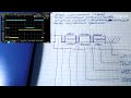
Sorry, no electrical schematics at the moment...
MCU can be clocked from internal 8 MHz RC-oscillator but external 8 MHz Xtal is recommended for precise timing. Internally clock is divided by 8, so everything runs at 1 MHz.
AVR fuse information
Fuses for ATmega328P with 8 MHz Xtal:
- CKDIV8 = 0
- SUT0 = 0
- CKSEL3 = 0
- SPIEN = 0
- EESAVE = 0
- BODLEVEL0 = 0
- all other at "1"
In hex form:
- low byte: 0x67
- high byte: 0xD7
- extended byte: 0xFE
For ATmega328P with internal RC generator:
- low byte: 0xC2
- high byte: 0xD7
- extended byte: 0xFE
Due to low clock MCU can run on voltages from 1.8 V to 5.0 V. But if 74HC595 is used for IO expansion, minimum supply voltage is 2.0 V.
Pinout for ATmega 48/88/168/328 MCU
Power supply:
- pin 7 (VCC): +5 V supply
- pin 20 (AVCC): +5 V supply
- pin 8 (GND): 0 V (common)
- pin 22 (GND): 0 V (common)
Clock input:
- pin 9 (PB6): 8.0 MHz Xtal
- pin 10 (PB7): 8.0 MHz Xtal
User input:
- pin 23 (PC0): (input) fast forward command ("0" active, pullup enabled)
- pin 24 (PC1): (input) play command ("0" active, pullup enabled)
- pin 25 (PC2): (input) record command ("0" active, pullup enabled)
- pin 26 (PC3): (input) stop command ("0" active, pullup enabled)
- pin 27 (PC4): (input) reverse play command ("0" active, pullup enabled)
- pin 28 (PC5): (input) rewind command ("0" active, pullup enabled)
Mechanism sensors:
- pin 4 (PD2): (input) takeup tachometer (pullup enabled)
- pin 5 (PD3): (input) home/stop position sensor ("1" active, pullup enabled)
- pin 6 (PD4): (input) tape presence sensor ("0" active, pullup enabled)
- pin 11 (PD5): (input) forward record inhibit sensor ("1" active, pullup enabled)
- pin 12 (PD6): (input) reverse record inhibit sensor ("1" active, pullup enabled)
Mechanism controls:
- pin 14 (PB0): (output) solenoid drive ("1" for energizing)
- pin 15 (PB1): (output) capstan motor drive ("1" for spinning)
Other (optional) controls:
- pin 2 (PD0): (output) playback mute ("1" for head amplifier to mute sound when not in playback)
- pin 13 (PD7): (output) record enable ("1" for enabling erase generator and switching amplifier to record mode)
For extended functions:
- pin 16 (PB2): (output) SPI latch (to pin 12 of 74HC595)
- pin 17 (PB3): (output) SPI data (to pin 14 of 74HC595)
- pin 19 (PB5): (output) SPI clock (to pin 11 of 74HC595)
- pin 3 (PD1): (output) TTL UART TX for debug @125000 8-N-1 (if enabled by [UART_TERM] define, not recommended for actual use)
Buttons that are not necessary can be not connected. If some mechanism sensors are absent or needed to be bypassed - corresponding pins should be left not connected or shorted to ground (see active signal notes).
Note
"Capstan motor drive" is optional and can be left disconnected.
Note
"Playback mute" and "record enable" are also optional.
Note
74HC595 extender is used for mode indication and can be not installed.
Pinout for 74HC595 extender
- pin 15 (bit 0): fault
- pin 1 (bit 1): tape presence (can be used for tape compartment illumination)
- pin 2 (bit 2): stop
- pin 3 (bit 3): recording
- pin 4 (bit 4): rewind
- pin 5 (bit 5): playback in reverse (or playback direction)
- pin 6 (bit 6): playback in forward (or playback)
- pin 7 (bit 7): fast forward
Important
"Solenoid drive" and "capstan motor drive" should be connected to some transistors that will switch current to solenoid and motor respectively. Usually those are powered from a separate +12 V supply.
- User-input processing is working fine
- Mode indicators are working fine
- State machine for CRP42602Y is working fine (some bugs in edge cases may still be present)
- State machine for Tanashin-clone is in draft state, not working
- Power saving procedures are working fine
- Finish Tanashin-clone support
- Add support for more transports
- Add feature toggling through command buttons in STOP mode (no pins for additional switches)
- Enable and use EEPROM driver for saving feature configuration
- Add more IO on SPI for more switches and indicators
Program copyright 2021-2023.
This program is free software. Licensed under the Apache License, Version 2.0 (the "License");